Finished build. Resistance issues. Need help troubleshooting.

To see if the meter is working, why not measure across one of the cathode resistors? I don't have an S.E.X., so I can't point to the terminal numbers. But you may be able to figure that out from the schematic and build instructions.

cheers, Derek
 
I had him do that already, which mostly worked, but not being able to resolve the output stage cathode resistances points to a sub-par meter or one that just isn't working properly.
 
So I bought an autoranging meter today. Here are the results.  Really not sure what to do.  I can't even measure the resistor on A9 or B9.  Maybe I used bad solder or something (Sn60/Pb40). but it worked fine for the glow test which would make me think it was something further into the wiring.  Any ideas would be great.

Terminal

1=0.4
2=OL
3=OL
4=OL
5=OL
6=OL
7=OL
8=0.2
9=0.3
10=OL
11=OL
12=OL
13=OL
14=0.1
15=0.4
16=OL
17=OL
18=OL
19=OL
20=OL
21=OL
22=0.1
23=OL
24=OL
25=OL
26=OL
27=OL

30=220
31=217
32=215
33=OL
34=OL
35=OL
36=OL

H1=0.4
H2=217.2
H3=OL
H4=215
H5=217
H6=OL
H7=215
H8=0

RCA Jacks
L center pin = OL  Ground tab = OL
R center pin = OL Ground tab = 0.4
 
Wow, I have been loosely following this thread and I think there is something fundamentally wrong with your testing procedure. And also the solder joints still look suspect. First does the solder have a rosin core flux? I can see at some joints it appears not. Next what kind of soldering iron do you have? is it adjustable or a fixed wattage? If a fixed wattage perhaps it is to low. I think a minimum would be a 40 watt iron. If adjustable crank it up. I run my Iron at 650-700 deg. F. very occasionally higher.
Next Please turn on your meter and set it to ohms and touch the tips together and note what the display shows. Post a pic. Next set the meter to DC volts which may be expressed by Vdc or a V with a solid line with a dashed line underneath find a 9 volt battery or a
AA or AAA battery and touch the probe tips to the battery terminals. Take a pic and post. It's easy hold the probes with your 2 hands and hold the camera with your third hand. ;D
So lets start there Then we will proceed ok?

 
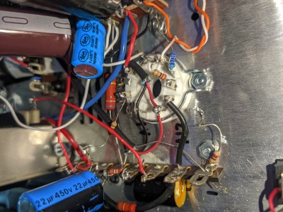
Let's start with the left grounding tab reading OL.

The left input jack/pot grounds all wire to 23, which you have with an OL, but it should be grounded.  23 attaches to 26, and your 26 is also OL, but should be grounded.  36 connects to 26, which both should also be grounded, but are not.  That's one entire side of the amp not grounded.  36 is also basically the output of the power supply, so it's a good idea not to turn the amp on until this is resolved.

On the other channel, the ground leaving 36 goes to 12, which also isn't grounded.  12 should go to 5 with a black wire, and that wire doesn't look well connected at 5. In that area be sure the drain wire on the shielded twisted pair wire is pushed down close to the chassis and the foil in that cable doesn't touch anything other than the chassis if necessary. 

Terminal 12 is wired to terminal 9, and you skipped that step.  I would imagine if you install the wire that should be there, things will start looking better.

 
OH I apologize I confused your thread with someone else building a Crack. So I will reread your thread to get it straight and get back to you.
 
Thank you very much Paul for breaking it down.  Thank you Thermionic as well.

This may be a dumb question, but how do I ground 23-etc.?  Is there something specific I should look for?  I went through the instructions over and it seems like everything is wired correctly.  I must be overlooking something.

I would imagine since they are all connected to 23 that it would be best to start there.
 
That's the part I don't understand.

How do I ground the left grounding tab?  My right one seems wired exactly the same and it is grounded.

Could it just need to be resoldered? Actually that would not make sense because the tab itself should be grounded
 
You're Awesome Paul.  Didn't think I skipped any steps but I guess I made a mistake at 3AM...

Here are my new resistance readings.  Much better but still something is off.

Terminal

1=0
2=OL
3=218.2
4=OL
5=0
6=OL
7=OL
8=0
9=0
10=OL
11=9.1
12=0
13=OL
14=0
15=0
16=OL
17=OL
18=OL
19=0
20=OL
21=OL
22=0
23=0
24=OL
25=OL
26=0
27=OL

30=108
31=108
32=108
33=OL
34=OL
35=OL
36=0

H1=0
H2=108
H3=OL
H4=108
H5=OL
H6=OL
H7=108
H8=0

RCA Jacks
L center pin = OL  Ground tab = 0
R center pin = OL Ground tab =  0
 
We'll start with terminal 3 reading as 220 ohms.  I mentioned another issue in post #25 that would likely clear this up.  It might also help to know if that resistance changes depending on whether or not you have tubes in the sockets.

Terminal 3 is shorting to some other terminal with a 220 ohm carbon film resistor attached to it.  I pointed out my concerns about this in post 25, and you need to go in there and push anything apart that's a bare lead that's touching anything it's not soldered to.
 
So I partially removed the 220 ohm resistors and the 1.5uF 630v metalized polypropylene capacitor.  The terminal is still reading 220 ohms.  Anywhere else I should check?

I also resoldered terminal 5 and moved the drain wire/foil away.
 

Attachments

  • IMG_20201226_155836.jpg
    IMG_20201226_155836.jpg
    2.7 MB · Views: 20
So the shielded twisted pair of wires that goes between A1/A12 and B1/B12 really needs to be run the way we specify in the manual.  You have it rubbing up against a lug on the 12 pin socket that sits at about 350V, and if the socket pin contacts the shield on the STP, serious destruction will occur.

Terminal 3 goes to ground through the primary of the output transformer, then the 680 ohm cathode bias resistor.  The bias resistor goes from 5 (where you have a good 0) to 11, where you have a reading that's not correct.

Is is possible that you're seeing 220K on terminal 3 rather than 220 ohms?  220K wouldn't necessarily be a problem. 
 
I really wish it was 200k.

I just emailed queen@bottlehead.com to see if I could send my unit in to diagnose.  I was hoping this would go smoother as I spent a lot of time on it.  I'm taking a break with my unit now.  Hopefully she gets back to me otherwise I will spend some free time trying to fix things.

I've built a couple pairs of speakers, this is definitely next level

Thanks again for your help.  Depending on her answer I might be asking more questions  :)
 
I am the contact for the repair service, and Eileen will be out of the office till the 4th.  We are doing a revamp to the repair service to straighten out some kinks we are experiencing, so I would recommend taking a short break, then getting back to it.

It may help to go through the manual in its entirety and carefully read each step, then check your work.  Some wires and connections are going to need to be moved to the proper spots for ultimate reliability, and you may discover some other issues that aren't so visible in the photos you posted.

-PB
 
Hey Paul,

Eileen actually got back to me and sent me the invoice for repair, which I have paid.  I am just waiting on the box to be shipped (I have no update yet). Just wanted to let you know.
 
Back
Top