Eros-2: I built it my way

georgeged

New member
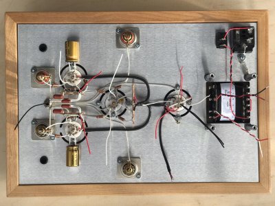
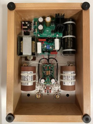
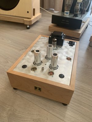
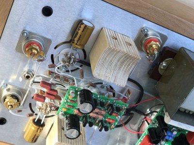
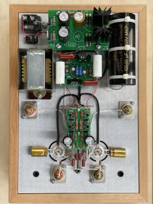
Just finished my Eros. Very happy with sound – very natural and warm. Thanks to all BH team for the great kit!

I made few changes / upgrades to stock kit:

1) Tube sockets are now premium machined Teflon
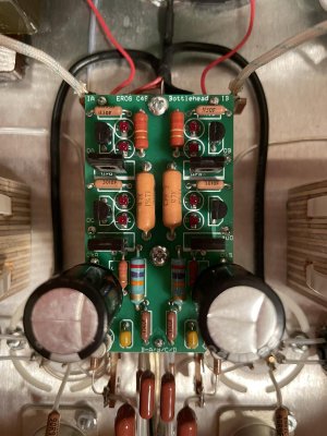
2) Most of MF resistors - Dale RN's, CF – Takman 0.5W
3) RIAA capacitors are matched within 1% tolerance to recommended values (I bought additional 10pcs of each value). 76.8K & 10.5K resistors (“ideal” values recommended by PJ) are Dale RN 0.1%
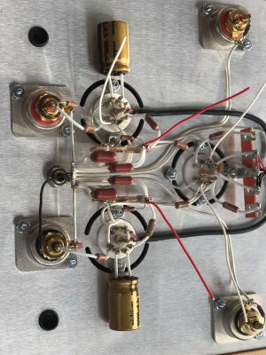
4) Almost all terminals (except 2 x 3-lug) are removed. I done it to make as less solder points as possible
5) Earthing is “star” type.
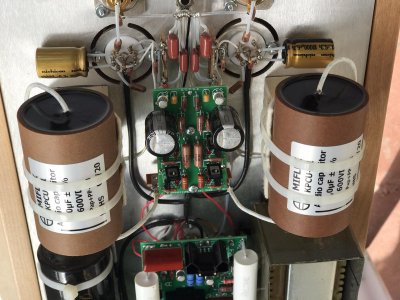
6) Most of hard wires are 1mm pure silver annealed silver wire (on the pictures the are in Teflon tubing; I had a piece from previous projects). Solder used is lead-free 4% silver.
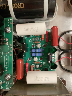
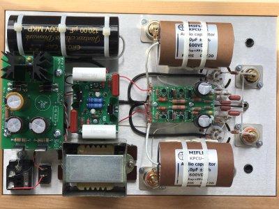
7) Power supply: 270R resistor replaced with C-7X choke; instead of 100uf electrolytic cap now is 120uf PP film.
8)    0.1uf capacitors on Shunt Regulator board are now CDE 942C
9) Output capacitors are MIFLEX KPCU-01 Copper Foil, Paper/Polypropylene-in-Oil 1uf 600V
10) And finally, NOS tubes are: EF86 – Valvo, E88CC - Tesla Gold Pins, ECC82 - RFT
 

Attachments

  • e01.jpg
    e01.jpg
    220.7 KB · Views: 165
  • e9.jpg
    e9.jpg
    214.7 KB · Views: 152
  • e8.jpg
    e8.jpg
    244.1 KB · Views: 135
  • e7.jpg
    e7.jpg
    195.9 KB · Views: 51
  • e5.jpg
    e5.jpg
    190.5 KB · Views: 84
  • e4.jpg
    e4.jpg
    241.2 KB · Views: 90
  • e3.jpg
    e3.jpg
    202.4 KB · Views: 119
  • e2.jpg
    e2.jpg
    201.3 KB · Views: 211
I think you will find that the RN60 27K cathode resistors you have installed will live a very short life (maybe a year) before the heat gets to them and destroys them.  It's possible that this particular resistor used in that spot will also scorch the PC board.

The same goes for the 47K resistors on that board, though I would expect the 27K resistors to blow out a good chunk of time before these do.  There are lots of fancy 2W rated parts you can get that fit here from Parts Connexion. 

The same goes for the ~220K resistors on the shunt regulator board above the 12AU7.


PB:
I think you will find that the RN60 27K cathode resistors you have installed will live a very short life (maybe a year) before the heat gets to them and destroys them.  It's possible that this particular resistor used in that spot will also scorch the PC board. The same goes for the 47K resistors on that board, though I would expect the 27K resistors to blow out a good chunk of time before these do.  There are lots of fancy 2W rated parts you can get that fit here from Parts Connexion.

PJ:
The 47K resistor carries significant DC and should be metal; film is more practical than bulk metal or non-inductive wirewound. But no carbon, it's more likely to be noisy. A 1.75-watt rating is acceptable. It can be 5%.

I bought Takman REY 1W, but they didn't fit - leads are too thick. I will search for something which will fit.
I'm confused as to the correct power ratings for the Dale resistor ranges. I thought military grade RN60 or its industrial grade equivalent CMF60 is 1W@70°. 47K used is RN70/CMF70, which, as far as I know, is 1.75W. Am I wrong?


georgeged said:
I thought military grade RN60 or its industrial grade equivalent CMF60 is 1W@70°. 47K used is RN70/CMF70, which, as far as I know, is 1.75W. Am I wrong?

quick look at the datasheets shows RN60 at .25W @ 70°C and an RN70 and .75W @ 70°C. The RN70 apparently used to be rated at 1W but was downgraded sometime in the past.
Reference: https://www.vishay.com/docs/31027/cmfmil.pdf
 
georgeged said:
I bought Takman REY 1W, but they didn't fit - leads are too thick. I will search for something which will fit.
When I run into that problem I will use my side cutters to cut the resistor leads to a point so they will poke into the boards.
georgeged said:
I'm confused as to the correct power ratings for the Dale resistor ranges. I thought military grade RN60 or its industrial grade equivalent CMF60 is 1W@70°. 47K used is RN70/CMF70, which, as far as I know, is 1.75W. Am I wrong?
CMF/RN60 resistors are 1/4W rated. 
CMF/RN70 resistors are 3/4W rated. 

That is the maximum power rating assuming the ambient temp around the resistor isn't over 70C.  The datasheet can be a bit confusing because it's so comprehensive.  If we consider the 47K resistor with ~150V across it, that's just under 0.5W of dissipation. For a CMF-70, that will give you +50C of temp rise, and we recommend staying under 100C total.  On a toasty PC board, you may go well over that.  Based on what's in the datasheet, they are rating the resistors to run up around 130C max, which would likely discolor the PC board and possibly burn up other components close by. 

The 27K RN60 dissipates less power, but it's smaller size means it will experience a similar temperature rise.  That part is in a pretty tight space, and I also noticed that you have the 100uF caps sitting right next to that part instead of bent over and hanging off the side, so heat will continue to be an issue there. 

We tend to suggest going with approximately triple the wattage that would be the bare minimum. 

Another trick you can use is to just buy a couple resistors of a higher value and parallel them together before sticking them on the board. 
 
Have a look at the Kiwame resistors, they are rated at 2 W and are pretty small.  I use them a lot...John
 
Natural Sound said:
How does it sound compared to the stock build?

From beginning It was build with upgrades.. Never heard stock model.. Right before I built Eros, I finished Aikido PH2 preamp (also with upgraded parts). Right after replacement of resistors mentioned by PB, I will spend time to compare those two. But my first impression is, that sound of Eros is warmer, and I like it.
 
@PB

Paul, I chose some replacement resistors on Mouser, but I think data provided on their site sometimes is not accurate (Dale CMF60 acc. to Mouser is 1W, CMF70 - 1.75W), so I would like to check with you. 
Can I use Holco H4P (acc. to Mouser 1W power rating) for 27K & 220K and Dale CPF3 (3W) for 47K?
Another option I found on PCX - PRP 1Watt metal films. But all 2W metal films they have are too big for PCB.
 

Attachments

There are different power ratings for mil-spec or regular commercial service, for the same reasons that we usually don't exceed 1/3rd of the regular rating - longer component lifetime/greater reliability. It's in the data sheet, though not very clear - the Vishay-Dale data sheet is intense!
 
The 27K HP-4 would be marginal by our standards.  Parts Connexion has an Amtrans and a TKD 27K/2W resistor, I'd pay a little more for the extra margin.  For what it's worth, the actual signal current will travel through the capacitor across this resistor and not so much through the resistor itself.  If the resistor pads on the PC board aren't giving you enough room, you can put the 27K resistors on the outboard terminal strips on each 9 pin socket (you'd have to add them back) between ground and an empty lug, then run an extra wire to the screen grid of each EF86 to make the appropriate connection.

The HP4 for the 220K would be OK.

The CPF-3 is a great choice.  I have a bunch of those in my stash. 

You're getting the real DIY experience here!
 
27K resistor: AMTRANS have Metal Oxide and Carbon Films. Most probably you recommend Metal Oxide ones, correct? If yes, what about Panasonic ERG-2 (2 watt)? I used them in DIY Nelson Pass amps - they are pretty good and small size too.
 
I would go for the carbon film.  We will use metal oxide resistors in our products where they don't handle signal current (mostly R2 on C4S boards) or where there may not be other good choices (sometimes for really low value/high power filament dropping resistors).  Since there's a big cap across the 27K resistors, I wouldn't be too concerned about using a metal oxide resistor there, but technically I would consider it a downgrade from the parts we provide. 
 
Resistors are changed. New ones are:
- 47K - Dale CPF3 3W
- 27K - Amtrans AMRT 2W
- 220K - PRP PR9372 1W

This resistors become really hot after an hour of listening. It was absolutely necessary to have more power here. Thank you PB!
 

Attachments

  • 3.jpg
    3.jpg
    232.7 KB · Views: 45
  • 2.jpg
    2.jpg
    190.6 KB · Views: 47
  • 1.jpg
    1.jpg
    209.1 KB · Views: 74
Back
Top