Eros 2 Help [resolved]

adeep42

New member
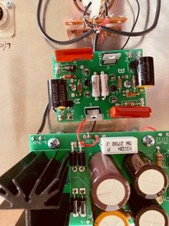
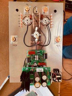
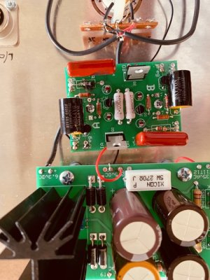
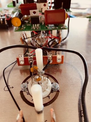
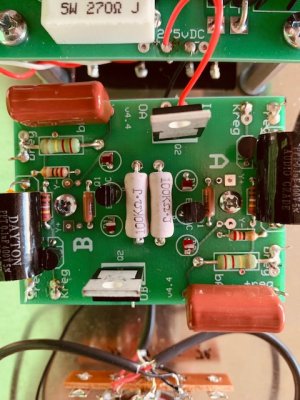
Working on my Eros2. Completed the Power Supply. All voltage tests on the money. Moved forward to Shunt Regulator.
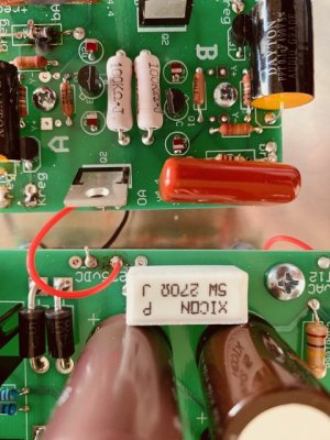
Got to voltage check and voltages were way off. As I was getting ready to make note of the readings, the resistor at AR4 sparked and fried itself.

Thanks in advance for the help.

Alan
 

Attachments

  • IMG_0444.jpg
    IMG_0444.jpg
    37.2 KB · Views: 17
  • IMG_0445.jpg
    IMG_0445.jpg
    67.8 KB · Views: 13
  • IMG_0446.jpg
    IMG_0446.jpg
    36.3 KB · Views: 13
  • IMG_0447.jpg
    IMG_0447.jpg
    63.5 KB · Views: 11
Hi Paul,                                                                                                                                                                                          Hope these work could go higher if your blog system will accept them.
 

Attachments

  • IMG_0444.jpg
    IMG_0444.jpg
    104.3 KB · Views: 21
  • IMG_0445.jpg
    IMG_0445.jpg
    133.1 KB · Views: 18
  • IMG_0446.jpg
    IMG_0446.jpg
    114.6 KB · Views: 18
  • IMG_0447.jpg
    IMG_0447.jpg
    121.6 KB · Views: 15
You have RC and R4 switched.

You can try replacing those parts and firing it up, but be aware that you may need to replace the whole board.
 
Thank you Paul. Not sure if I'll have time to remove the offending resistors today and then assess the board. Will respond after. One way or another I'll need some resistors (at least one).
 
Hi Paul,

Looks like I need a new board. If the solder pads were not wrecked before, I wrecked them removing the bad resistors. I'll write to Eileen at replacement parts.  Please coordinate with her so that I get every thing I need particularly those parts that you think might not survive being removed and replanting.

Thanks in advance,

Alan
 
Hello Paul,

All parts and PCB arrived. New Shunt Regulator built and installed. No fires during voltage checks however while voltage check on B side was 207VDC, A side was 300VDC. Picture of build below. Your thoughts please.

Thanks,

Alan


Attachments

  • IMG_0458.jpg
    IMG_0458.jpg
    109.2 KB · Views: 18
Reflow the center leg of each MJE5731A.  They take a lot of heat to solder properly, and the output being about equal to the input on a C4S is usually caused by that leg having a cold joint.
 
Back
Top