dude, where did my power go?

Stalemate

New member
Hi,
I've assembled the stereomour II kit, following the excellent instructions provided.

All my resistance tests are a-ok, but when I do the power tests, I get very low values, so low that I was wondering if my multimeter is acting up, but control tests show expected results, so I'm a bit lost here.

I've checked the transformator and gets the expected results from "secondary power check", I've checked the wiring, but the first check comes out at 2 VDC, while the expected result is 360something.

how do I troubleshoot this? I don't dare connecting it to anything, since as far as I know, there are 358 unaccounted Volts in there somewhere...

I'm a newbie, so be nice...
 
Hm, so after doing a quick "RTFM" on what to look for, I turned my attention to the C4S-board. I measured the transistors, and got these measurements on the "bipolar" - 1-3 ok, 1-2 null, 2-3 ok, 3-1 ok, while the other didn't give any measurements on any combination - so is this consistent with what I describe?

oh, and the leds are dark.

any help appreciated!
 
Do a complete voltage check and post any terminals that are off by more than 10%. PB or someone else at Bottlehead will help you resolve the problem. But they need the voltages that are off plus the terminal numbers to troubleshoot.
 
Thanks for the advice!
I managed to break one of the mje-transistors when I was measuring its function, so I need to order some new ones :(

I'll be back!

v
 
I rebuilt the C4S and measured the function of the transistors ok, I also doublechecked the solders, and everything seems fine.

I then proceeded to check my solders, and replumed where I saw it necessarry. All the resistance checks are ok, so I plug in the tubes and power, and get the following:

1: 2VDC
2: 2VDC
3-18 : 0 VDC
19: 2VDC
20: 2VDC

The rest are dead, 0 VDC
I rechecked the wiring on the OT and PT (connectivity + config) ok

The tubes light up, I'd say a bit weak, but I haven't seen an functioning amp,so I couldn't say whether it's within the norm.

please advise..

best regards
Vegar
 
Perform the power transformer voltage measurement for the 160V terminals and let us know what AC voltage you get there.

-PB
 
Thanks Paul,

I'm actually not able to measure any voltage over those terminals.

I've double checked my configuration, I have 236VAC in the mains, (which I'm able to measure on terminals 2-4)  so I configured it by connecting terminal 1 to 6, I've checked my soldering for connectivity, and it's ok.

what more tests can I do?

br
Vegar

[edit]
When I short out the 160V (19-20), the fuse blows, which should mean there is something touching something else in there.

[/edit]
 
You really don't want to test the transformer by shorting out the high voltage secondary. That can damage it. I suggest going back to the power transformer secondary voltage tests and check all of them - 19 and 20, 15 and 9, 14 and 11.
 
So I did - and there is no power there. Shorting out the 19 and 20 was an accident, I was clumsy and managed to touch both poles with the multimeter.

v
 
Hi,
Yes I did, The measurements are neglible, the multimeter a very low current (~0.2 mV) on both.

So to summarize, I'm able to trace the 236 VAC from the wall, via the 46-48 mounts to pin 2 and 4.
I've connected pin 1 to pin 6 to configure the transformer for that current. I'm able to measure 0 ohms on all my connections, meaning the solder and cable is ok, but none of the secondaries gives any reading, other than flutter on the meter. What am I missing here?

thanks
V
 
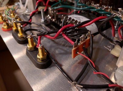
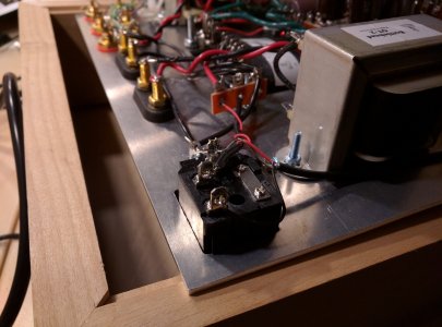
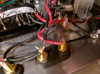
Post a photo of your black and red power supply jumpers that attach from the terminal strip to the set of 6 lugs.
-PB
 
Hi,
Here you go

v
 

Attachments

  • IMG_20160203_215111.jpg
    IMG_20160203_215111.jpg
    2.1 MB · Views: 204
  • IMG_20160203_215412.jpg
    IMG_20160203_215412.jpg
    3.1 MB · Views: 172
  • IMG_20160203_215728.jpg
    IMG_20160203_215728.jpg
    3.9 MB · Views: 172
These symptoms don't make sense. You say your tubes glow, but you are reading 0.2mV on the heater windings. Are you sure you are properly switching between AC and DC as needed?

Also a lot of your solder joints look problematic. The wires on the binding posts look like they would pop off without much effort. This won't solve the power issue, but do need to be addressed at some point. The IEC inlet and terminal 6 on the transformer also don't look like strong joints. Reheating all your power input related joints might be a good first step. Some of them have a lot of solder, but not clean solder joints. Reheat them so the solder flows smooth. The joints that are barely hanging on may need some more solder while reheating.
 
fullheadofnothing said:
These symptoms don't make sense. You say your tubes glow, but you are reading 0.2mV on the heater windings. Are you sure you are properly switching between AC and DC as needed?

Also a lot of your solder joints look problematic. The wires on the binding posts look like they would pop off without much effort. This won't solve the power issue, but do need to be addressed at some point. The IEC inlet and terminal 6 on the transformer also don't look like strong joints.

Good morning, Sir. I am absolutely not. After measuring the transformer using this new _Alternating_ current measuring method, I'm happy to report that the Transformer is ok.

God that was embarassing. Apologies all around.

the terminal 6 is soldered from both sides, so it should be ok, thanks for the advice on the binding posts.

Now, I manage to trace the (_alternating_)current all the way to the tube sockets, but from there I get a bit uncertain on how to take it from there.

The measures are the same as well, when using the _Direct_ current measuring setting.

thanks.
v
 
Back
Top