Hi,
I’m working my way through my Kaiju build and am running into issues with the voltages on 32U and 46U.
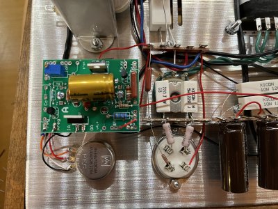
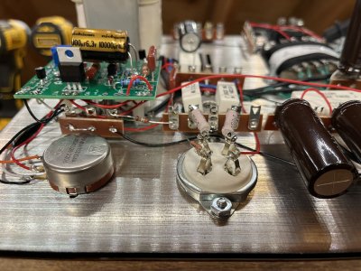
On the A socket board:
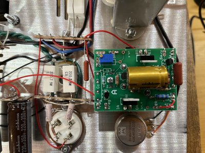
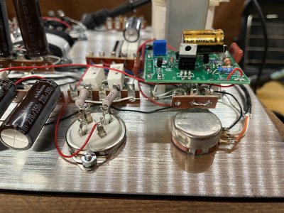
On the B socket board:
Turning neither pot changes 32U/46U significantly.
I did noticed that it looks like neither LED in D2 on the B sides of the boards is lit.
I tried reflowing everything on the two boards, which made no difference. Can you recommend next steps for troubleshooting?
Thank you for you help!
I’m working my way through my Kaiju build and am running into issues with the voltages on 32U and 46U.
On the A socket board:
- IA: 506v
- OA: 302v
- 32u: 3.9mv
On the B socket board:
- IA: 506v
- OA: 307v
- 32u: 16.3mv
Turning neither pot changes 32U/46U significantly.
I did noticed that it looks like neither LED in D2 on the B sides of the boards is lit.
I tried reflowing everything on the two boards, which made no difference. Can you recommend next steps for troubleshooting?
Thank you for you help!