Crack transformer power not reading 6.5 at pins 7 and 9 [resolved]

edward1171

New member
In fact, it's somewhere between 0.003 and 1.7 depending on where on pins 7 and 9 I touch.

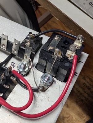
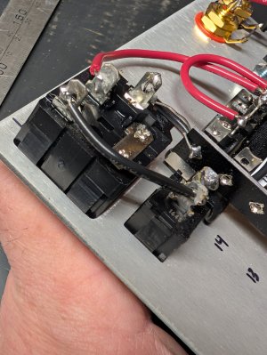
I'm at the first "plug it in and make sure you're good to go" stage where you just check for stepped down power at 7 and 9 on the transformer.

It looks like the plastic loop around the base of 9 isn't smooth. Possible heat damage?

Do these come messed up sometimes?
Me causing heat damage is totally a possibility.


I'm reading 120 everywhere else I should be, ground is good, wires are in the proper spots, solder makes solid connections, used two testers (Klein and fluke 15b) and got a friend to check it out just in case I'm missing something.

It's got to be something either in the transformer or with pins 7 or 9 coming out of them.


Can I get a new one?

Or am I overlooking something silly?


I can't upload on android or Mac OS so here's an imgur link
 
Last edited by a moderator:
Can you post a couple photos? If you’re just starting the build and haven’t gotten past some of the basic steps then we’ll swap you transformers.
 
The silly thing that sometimes gets overlooked is the meter. There are a bunch floating around that are really meant for home improvement, so they will read AC voltages really well between about 100V and 300V, but when you get down to single digit voltages, that just comes across like 0V.
The transformers also get encapsulated in varnish, and it's possible that there's varnish on those terminals, so you can scrape on them a bit with a small flathead screwdriver to expose some clean metal.

You'd also want to set your meter to resistance and be sure that you see close to 0 ohms between 7 and 9 (with the transformer not energized of course).
We used a few leads, one set has been my buddy's for decades and he does this stuff.
I was using a fluke 15B+ I'm under the impression that's decent. It was the same with the Klein and with separate leads.
I'll check resistance between 7 and 9 tomorrow
 
The silly thing that sometimes gets overlooked is the meter. There are a bunch floating around that are really meant for home improvement, so they will read AC voltages really well between about 100V and 300V, but when you get down to single digit voltages, that just comes across like 0V.
The transformers also get encapsulated in varnish, and it's possible that there's varnish on those terminals, so you can scrape on them a bit with a small flathead screwdriver to expose some clean metal.

You'd also want to set your meter to resistance and be sure that you see close to 0 ohms between 7 and 9 (with the transformer not energized of course).
Imgur link to a visual of the 7 to 9 resistance
 
I would just double check that the amp fails the glow test. If it does, we will need to swap out your power transformer.

It's also worth noting that you are not at the "Power Transformer Secondary Test", but rather you are on the "Heater Wiring" section.

If your initial tests on the power transformer showed ~6.5V on that power transformer winding, then it went to 0V after the heater wiring was installed, that would be extremely valuable information to have, and could allow us to help prevent the destruction of another power transformer...
I disconnected green lines from 7 and 9 and measured and there was still no V.

I measured the under side of the plug and it was 13 volts between L and N when plugged in.
The instruction suggests that it should read 120 and it did the last I checked.

I assume there's an issue with the IEC Power inlet or cable.

I checked resistance in as many ways as possible and here's what I found.

Between the male and the female ends of each line of the provided power cable there was a maximum of 0.5ohm
None of the leads gave anything other than 0.L when I measured the males and females that didn't match.


In the IEC power inlet that goes through the aluminum plate, with the ground considered "down" for explanation sake. I'll use left / right designations for the outside of the inlet.
I'll use the designations the instructions have you wrote on the aluminum for the inside.


I got the following readings:
-Between right prong and L, N and E was a 0.L ohm (I assume right and L would have and ohm reading)

-Between left prong and N o.2ohm (I'm assuming this is a direct connection)

- Between the left prong and L 10.5

Between the L and N prongs on the IEC, 10.5 ohm

Between ground and E 0.5ohm

I measured the fuse resistance and it jumps around a lot If you touch the sides but if you touch the ends it settles at 0.3 ohm.
The filament looks intact.


So it seems as though the left prong is connected directly to N and has 10 ohm resistance to L.
This is the same resistance between L and N in the wiring step after I've connected the power for 115- 130v (everything here reads between 119 and 120 out of the wall).

Is it possible there's a faulty connection between the right prong and the fuse?

I got the photos to work on this one.
Maybe you can see something I can't but this is what it looks like.
 

Attachments

  • PXL_20251020_221950159.jpg
    PXL_20251020_221950159.jpg
    1 MB · Views: 6
  • PXL_20251020_222003012.jpg
    PXL_20251020_222003012.jpg
    1.1 MB · Views: 6
Last edited:
I may be off base here but are you sure that the fuse is in the correct position, there are two possibilities
 
There’s one that is boxed in and there’s one that’s more like a clip. The clip hold the active fuse and the boxed in one holds a spare.
 
Back
Top