Crack Speedball hpjun's trouble shooting thread [resolved]

hpjun

New member
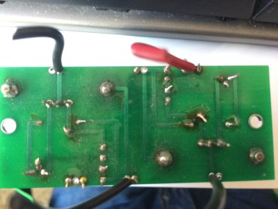
I messed up my install of the speedball, I have some waxy resin substance that is covering the connections of the board making a bridge (not sure if its conductive it came out of the soldier). I also am not sure if I installed the LED's right since I didn't install them upside down. Also I need more wire for the install. It was difficult before because my soldering iron was bad, now I have a good one.
What do you guys suggest I do?
 

Attachments

  • IMG_2576.JPG
    IMG_2576.JPG
    1.1 MB · Views: 302
Looks like the center leg of the upper 2N2222A might need a touchup with the new iron. The flux residue doesn't look like anything to worry about. Touch up that transistor leg and anything else that might look shaky and try it again. If that doesn't work you might need to get those LEDs out and see which way they are facing.
 
The "waxy resin substance" is flux. It is non conductive. But if you want to clean it off, a little isopropyl alcohol, a q-tip and a bit of light scrubbing usually does the trick.

I have successfully removed the diodes from the board without damaging them. I use a pair of needle nose pliers to gently grasp the LED. The solder connections on the LED are close enough that you can arrange the soldering tip and heat both connections at the same time. Once the solder liquifies simply pull the LED out of the board. It takes a little practice but this technique works great. Just don't force it. Once enough heat is applied the LED will practically fall out. If you accidentally break them replacements are available here. http://bottlehead.com/product/hlmp-6000-leds/

EDIT: Doc B. Beat me to it.
 
Alright I'll see what I can do to touch it up. I don't want to mess the stock crack until I get the speedball looking good first.
 
Removing the leds are tricky. I might just snip them off and order new leds. Is there a way to test the led direction from a multi meter? I have a lot of functions on my meter.
 
hpjun said:
Removing the leds are tricky. I might just snip them off and order new leds. Is there a way to test the led direction from a multi meter? I have a lot of functions on my meter.

You can look at the silver banded end to easily determine directionality.
 
I remember when I installed the speedball it worked but it had channel imbalanced and sounded generally worse.

If the leds where incorrect there won't be sound right?
 
If the leds are installed incorrectly they won't light and the voltages will be off. It will sound bad or most likely not work at all on the channel that is wrong.
 
Well it's an hassle to reinstall the speedball just to check.

I already ordered 8 new leds I'll just pull them all off now and reinstall.
 
I didnt change any leds they where already correctly installed since they lit up.

Installed the speedball and did the Voltage check and the values came out with in range so i gave it a listening test. I turned the volume about half and I hear buzzing in the left driver and when i turn up a little more the right driver has the buzz too but at a lower volume. Then i noticed the buzz is quietly audiable without headphones plugged in it's coming from the power supply area or the caps.

My music sounded Ok, except for the buzz. My crack was quiet before the speedball.

1 77
2 181.3
3 0
4 181.3
5 81.8
6 0
7 107.1
8 0
9 110.6
10 0
11 0
12 0
13 181.1
14 0
15 199
19 85
20 0
21 217

A1 81.6
A2 0
A3 1.53
A4 0
A5 0
A6 76.7
A7 0
A8 1.53
A9 0

B1 76.8
B2 180.7
B3 106.6
B4 81.6
B5 180.4
B6 110
B7 0
B8 0

 
It's quite time consuming to go through a list of voltages and try to determine which might be in or out of spec. If you could post only the voltage readings that are out of spec, the terminal it was taken at, and what the manual says it should be we can usually come up with some suggestions little more quickly.
 
2nd column is my measurements, 3rd column is the manual's measurements, 4th column is the difference in values, I also put in bold the big differences.

1 77 75 103%
2 181.3 170 107%
3 0 0
4 181.3 170 107%
5 81.8 75 109%
6 0 0
7 107.1 100 107%
8 0 0
9 110.6 100 111%
10 0 0
11 0 0
12 0 0
13 181.1 170 107%
14 0 0
15 199 185 108%
20 0 0
21 217 206 105%
A1 81.6 75 109%
A2 0 0
A3 1.53 1.56 98%
A4 0 0
A5 0 0
A6 76.7 75 102%
A7 0 0
A8 1.53 1.56 98%
A9 0 0
B1 76.8 75 102%
B2 180.7 170 106%
B3 106.6 100 107%
B4 81.6 75 109%
B5 180.4 170 106%
B6 110 100 110%
B7 0 0
B8 0 0
 
Also the voltages are not balanced from right and left channels. I had that problem before speedball too.
 
Those readings look like pretty typical variations from tube to tube, and they aren't really out of spec far enough to be a major concern. I think the best approach might be to go back over all of the new connections made from the PC boards to the tube sockets, since this noise seems to have appeared after those parts were installed. Buzzing usually indicates a ground connection that is not perfect. If you have some other tubes you might also try them to see if the noise goes away or changes in any way.
 
Ok and the buzz sounds like the same kind of buzz from power supply. It's faintly audiable without headphones plugged in. I was thinking it might be picking things from the vibrations? I will do another resistance check and go over any soldier connections that are different and go over the ground on the speedball.

This is my second speedball install and it had similar problems before left channel had a buzz as well.
 
You might try tightening up the power transformer mounting screws a bit. Sometimes that will eliminate the kind of mechanical buzz you hear.
 
I tightened up the power supply to the chassis and noticed a small improvement. Before i had to turn it up to about half way 6 o clock to hear a buzz, now I need turn it up to about 7 o clock to hear the buzz. The nuts are really hard for me to reach and tighten since I don't have the tool for that size nut but I will keep trying and I'll buy some tools tomorrow.
 
It was those long wires that ran from the rca input to the potentiometer! I noticed a good reduction in noise when I manually moved those wires farther away from the noisy powersupply. Is the powersupply supposed to be this noisy? Having the RCA inputs near the powersupply isn't an optimal design. I didn't do that good of a job braiding those wires though and probably would have made a difference. Knowing how bad the power supply can interfere with the sound just doesn't sit well with me. I feel like rerouting all wires carrying audio signals as far away as possible from the powersupply. Maybe I will drill 2 holes and install the rca near the potentiometer and away from the powersupply. Are there good ways of isolating the power supply noise?
 
Rather than moving your RCA sockets you could replace the stock red white and black wires that run from them to the potentiometer with some high quality four core screened cable from Belden or Mogami as a number of other Crack builders have your only going to need a short length.

Or just re braid what you have and save some cash its dead easy to get a nice braid.


https://www.youtube.com/watch?v=qxJY4lna5q0


The braided input wiring, and the tightly twisted filament heater wiring is done to reduce noise.  If built exactly as shown in the manual the amp will be completely silent.  Shielded input cabling is better again, but fine multi stranded cable like that is much more difficult to work with than the solid core wire supplied.
 
Back
Top