Crack Build - #4

ALL212

New member
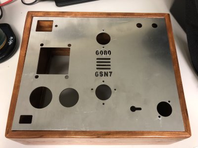
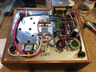
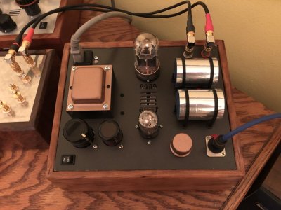
Due to a misunderstanding between my brother and I he built a base angled the wrong way and it's too big for the standard Crack plate.  Not wanting to leave it behind and with the recent sale I bought another Crack to build.  This time with a redesigned/resized plate to accommodate this odd combination.

I was playing with the idea of doing alternate tubes but I don't think complicating this would have been wise.  I am going to use the 6SN7 in the 12au7 slot.

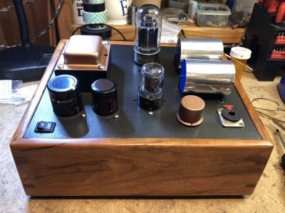
I've got cleanup and a bit of grinding to get the plate laid in the cutout (the plate is straight, the box cutout is not).  I'll probably go with my standard black plate with copper highlights - we'll see what's in the paint cabinet and go from there.


Attachments

  • plate.jpg
    plate.jpg
    1,007.1 KB · Views: 59
ALL212 said:
(the plate is straight, the box cutout is not)
Those perfect miters on our alder bases often get taken for granted!  A belt sander will adjust that panel to fit pretty easily. 
 
I have also noticed that if you play really good music, people tend not to notice minor woodworking issues  8)...John
 
;D

Turning down the lights helps also!!

For the group -
I'm going to change the value of the last PS cap to 450uf so I can drop the value of the output caps (will be a pair of ClarityCap ESA/CSA 39uf for 78uf total).  Is changing the value of the 2nd PS cap something to entertain or is that a moot point?  All my headphones are 300 ohm so I can work towards that final value.
 
Should everything go well we should end up with the attachment below.
Heater test passes - on to input wiring.
 

Attachments

  • IMG_7427.JPG
    IMG_7427.JPG
    1.3 MB · Views: 67
  • IMG_7428.JPG
    IMG_7428.JPG
    1.5 MB · Views: 46
Everything checks except volts at terminals 2 and 4 are 215v
It plays and sounds great but should I go back and recheck something?

Pics later.
 
No... I almost wired it for 115 - 130.  I moved the red wires over one terminal.

Wow...  :-[  Corrected that and now 180v at 2 and 4.

Exhibit A and B below will illustrate how NOT to wire the transformer and then how to do it as directed.
 

Attachments

  • IMG_7443 - Copy.JPG
    IMG_7443 - Copy.JPG
    1.2 MB · Views: 30
  • IMG_7442 - Copy.JPG
    IMG_7442 - Copy.JPG
    1.3 MB · Views: 31
Ferrite beads on the power wiring! Cool. Have you done, or will you do, with/without comparisons to see if and how they affect the sound? I'd be interested in your impressions.

cheers,

Derek
 
I forgot my disclaimer.

Not everything that is installed has a specific purpose.  The ferrite beads were there, we had a discussion and it was decided that they would be used.  Yes...ferrite beads speak to me.  :o

 
What ferrite beads would keep out is unlikely to pass through the power transformer.  If we used a toroidal mains transformer, that might not so much be the case.
 
The build dissertation, Top plate - picture include.

The base is at an angle.  Not sure I would do that again.  It complicates things underneath a bit.  I mounted the choke right at the border and since the plate tips back...well, it's tight.

The silver caps are Clarity Cap ESA 39uf's and there are a pair of Clarity Cap 39uf CSA's under them in parallel for a total of 78uf.  I think the supplier ran out of ESA's (on sale - 50% off!) and then shipped the CSA's.  It worked out and I got a deal on the CSA's as they charged me the same @ 50% off.  There are some rubber bumpers under those caps to keep them off the plate.  I liked the silver on top - other than that no selection on which caps went where.

I had the tube names cut through the plate as additional cooling and to indicate who goes where as they are both 8 pin sockets (6SN7 used instead of the 12AU7).  I like the look of the PS caps poking up from underneath.  PS cap final is a 470uf Mundorf MLytic HV and the other is a JJ 220 uf.

RCA jacks in the back are Cardas GRFA

Some of this was leftovers from prior projects.  I had the Neutrix jack, knob, power switch, RCA's and the JJ PS cap left over from other projects.
 

Attachments

  • IMG_7444_1.JPG
    IMG_7444_1.JPG
    152.8 KB · Views: 32
  • IMG_7438_1.JPG
    IMG_7438_1.JPG
    130.8 KB · Views: 44
The build dissertation, Bottom of the plate - picture include.

The power supply is changed so that I can use smaller output caps.  First cap is standard 220uf, 2nd cap is a JJ 220uf tipped with a 2.2uf Wima and final cap is a 470uf Mundorf MLytic HV tipped with a Solen 4.7uf film cap. In place of the 2nd resistor I've installed the Triad CX-7 choke.  1st resistor is a Mills that I had and it matched the 270 ohm value needed.  Diodes were replaced with the diode board and Cree Schottky diodes.  As someone noted I did put ferrite beads in but it's also been mentioned that they serve virtually no purpose with the transformer supplied. 
Wiring is mostly cotton wrapped ( https://www.tubedepot.com/products/20-ga-solid-cloth-wire-600-volt-rating ) or stock.
Power switch is a Cherry with the on/off markings.
I did use a 8 pin socket wired for 6SN7 tubes instead of the 9 pin 12AU7 socket.  I've liked the sound of the 6SN7's since I first tried them with the socket adapter.
Input wiring is Mogami 2534.
Volume is an Alps blue mounted on a circuit board.  Putting together the connectors isn't difficult but takes a steady hand (lay off the coffee!).  I find it easier than trying to solder onto the straight pins.

I'm going to try and resist putting in the Speedball so I can get a feeling for the sound.  I've installed the standoffs and found that doing that as you build insures that there are no difficulties getting those in later.  In other builds I streamed the speedball in but with all of the components moving on this build I elected to do that later.

Plate was designed by me and cut by laser.  I drilled some holes later to accommodate the capacitors and wire ties.  Each of those holes has a rubber grommet and under the output caps are rubber bumpers.


Attachments

  • IMG_7441_1.JPG
    IMG_7441_1.JPG
    138 KB · Views: 44
  • IMG_7446_1.JPG
    IMG_7446_1.JPG
    128.8 KB · Views: 24
  • IMG_7450_1.JPG
    IMG_7450_1.JPG
    118.4 KB · Views: 29
  • IMG_7447_1.JPG
    IMG_7447_1.JPG
    184.4 KB · Views: 34
Back
Top