Crack-a-two-a Build Log

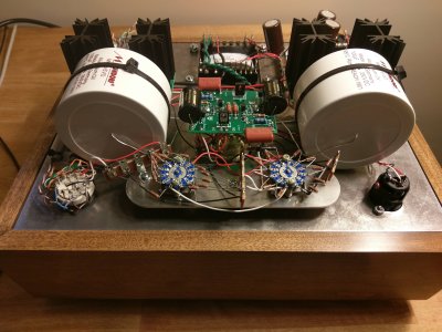
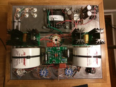
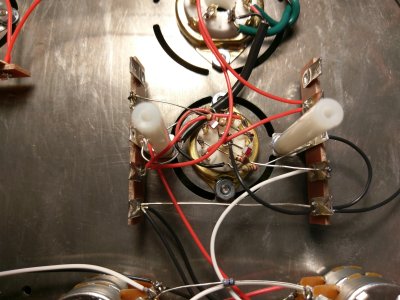
Uh oh, hope it won't cause problems. Here is a picture, for both A2 and A7 the resistor body is about 8-9mm away.  If necessary I could desolder everything and flip the socket, might get me another few mm.

UPDATE: I am reorienting the socket 180 degrees, should solve the issue.  Thanks for the help, PB.
 

Attachments

  • IMAG0113.jpg
    IMAG0113.jpg
    2.9 MB · Views: 96
UPDATE: I am reorienting the socket 180 degrees, should solve the issue.

Using the stock socket in the as designed position will solve the issue. Rotating the socket 180 degrees is begging for a miswire.
 
Thanks, I checked and double checked the wiring of the 9-pin, rotating it 180 got the resistors where they needed to be.

Here is a picture of the stock circuit.

I am having a weird issue with my resistance checks, in that I cannot measure them at all.  I have my negative lead on the #8 near the IEC, I get a 0 Ohm reading at the power transformer screw, then cannot measure anything across the transformer.  Checking for continuity also gives no result at any transformer terminal.  This is consistent across two different multimeters and they are set to the correct range for each reading.  Fuse is not blown, all tests up to this point were passed, reflowed all of the joints at the transformer, power switch, ground bus, IEC.  Feel pretty dumb like I'm missing something obvious here, any suggestions?  I've been staring at this circuit too long.
 

Attachments

  • IMAG0114.jpg
    IMAG0114.jpg
    2.7 MB · Views: 124
L0rdGwyn said:
I have my negative lead on the #8 near the IEC, I get a 0 Ohm reading at the power transformer screw, then cannot measure anything across the transformer. 
Only the transformer screw with the ground tab has to be 0 ohms.

I checked the resistance readings in the manual and I do not see any resistance checks for any power transformer terminals.
 
Caucasian Blackplate said:
Only the transformer screw with the ground tab has to be 0 ohms.

I checked the resistance readings in the manual and I do not see any resistance checks for any power transformer terminals.

Ah yes, knew it had to be something dumb on my part, this is what happens when you are working night shifts and build this circuit in two sittings.  Thanks for humoring my stupid question regardless, PB.

All resistances and voltages are within spec - time to give this baby some head-time!

Here are some beauty shots, really pleased with how it came out aesthetically.

COMING SOON: TwoQuiet attenuator upgrade, Bottlehead Power Cord, and ridiculously large output caps :)
 

Attachments

  • IMAG0115.jpg
    IMAG0115.jpg
    1.2 MB · Views: 84
  • IMAG0116.jpg
    IMAG0116.jpg
    1.1 MB · Views: 50
  • IMAG0117.jpg
    IMAG0117.jpg
    1.3 MB · Views: 64
I’m in the middle of a tricked out Stereomour build - maybe i’ll follow your example!  I’m planning on keeping the brushed aluminium top plate as is, but could you share as to how you got the mirror finish?
 
faskenite said:
I’m in the middle of a tricked out Stereomour build - maybe i’ll follow your example!  I’m planning on keeping the brushed aluminium top plate as is, but could you share as to how you got the mirror finish?

Certainly!  First off, it was a lot of work.  Took some serious trial and error, had to start over multiple times.  I first sanded down the top to remove the machined texturing, started with 180 grit, then 240, 320, then 400.  This step is really important, if you don't get it all the way down, you will see the grooves in your final finish.  I then used a benchtop buffing tool and buffed with Brown Tripoli compound, a good once over the whole plate.  From there, I did a full once over with white diamond buffing compound, then went back around and spot buffed with the white diamond.  After all of that, I polished the top with White Diamond liquid metal polish to finish.  Also had to clean in between each round to remove buffing compound.  Ultimately I am happy with the result, but getting it to a perfect mirror just isn't feasible, the aluminum is very prone to scratching so there are imperfections (even wiping with microfiber can leave visible micro-scratches).  I would only recommend doing it if you have a lot of patience, it definitely tested mine.
 
Added the Mundorf caps and TwoQuiet attenuator.  Here are some pics of the final circuit.


Attachments

  • IMAG0119.jpg
    IMAG0119.jpg
    783 KB · Views: 97
  • IMAG0118.jpg
    IMAG0118.jpg
    2 MB · Views: 140
I know that PB worked hard to make sure there was a ton of room for special caps and other such things - looks like you used up all the space with those Mundorfs! Looks good!
 
Paul Joppa said:
I know that PB worked hard to make sure there was a ton of room for special caps and other such things - looks like you used up all the space with those Mundorfs! Looks good!

Thanks Paul!  They just fit, had to change the orientation of two terminals in the TwoQuiet, but hey it works!
 
Alright, final entry in the build log.

Finished my Bottlehead Power Cord.  Had a little mishap with the adhesive heat shrink included in the kit, so I had to replace the shrink and the tubing.  Since the plugs were both goopy, and everything else on this build has been customized, decided to go ahead a pimp out my cord a little bit: got some nice fabric woven tubing, 4:1 heat shrink, and a Wattgate AC plug.

After finishing the top coat on the base, I buffed it to a high gloss (not sure if it comes across in the pics with the lighting).

Well that's it!  Build complete.  Below are some pics of the cord and some shots of the final build.  Also has the 6SN7 adapter I put together.

Thanks for checking out my log!  Happy listening.
 

Attachments

  • IMAG0140.jpg
    IMAG0140.jpg
    1.1 MB · Views: 59
  • IMAG0141.jpg
    IMAG0141.jpg
    999.8 KB · Views: 69
  • IMAG0144.jpg
    IMAG0144.jpg
    577.6 KB · Views: 63
  • IMAG0145.jpg
    IMAG0145.jpg
    1.6 MB · Views: 63
LOrdGwyn, thanks for documenting your build. Really enjoyed your pictures. Would you mind describing the sound of the Crack-a-two-a compared to your Crack+Speedball? Also please state the headphones and tubes used for the comparison. Thanks in advance.


-Raymond
 
Raymond P. said:
LOrdGwyn, thanks for documenting your build. Really enjoyed your pictures. Would you mind describing the sound of the Crack-a-two-a compared to your Crack+Speedball? Also please state the headphones and tubes used for the comparison. Thanks in advance.


-Raymond

Hey Ray!  Thanks for checking it out.  And absolutely.  Keep in mind this is from memory (I no longer have my BHC+SB), so I can't give you a true A-B comparison.  My standard setup on my BHC+SB was a Western Electric 421A power tube with a Mullard CV4003 driver.  Here are my thoughts while listening with the same configuration on the Crack-a-two-a but with General Electric 5-star 6005 shunt tubes.  My two main sets of headphones are my Beyerdynamic DT1990 Pros and my Sennheiser HD660S.  I would say the things that stick out with the Crack-a-two-a is an increase in clarity, better bass definition, and wider sound-staging.  I think there is also better separation between sounds/notes, which may be what Doc is referring to when he says the power supply gives a blacker background.  I feel that the presentation is also more detailed, more microdetails, but its hard to say without a direct comparison.

Hope that helps!  Sorry I can't be more specific without the Crack to do a side-by-side, I don't want to be misleading, but let me know if you have any questions.
 
LOrdGwyn, I think you gave a perfect A-B comparison between the Crack+Speedball and Crackatwoa. I currently have both amps and a pair of HD 650's with the Crack being fully modded. I think you were spot on. Although the Crack+Speedball is very nice, the Crackatwoa offers a lot more. Music sounds like real life, like you're in the studio or concert with the artists. I can only imagine what these sound like with HD 800S's. Definitely worth every penny. To my ears they sound and look like a $1500+ amp.

Very nice amp btw. I love what you did with the chassis! Awesome work :)
 
Jimb0 said:
LOrdGwyn, I think you gave a perfect A-B comparison between the Crack+Speedball and Crackatwoa. I currently have both amps and a pair of HD 650's with the Crack being fully modded. I think you were spot on. Although the Crack+Speedball is very nice, the Crackatwoa offers a lot more. Music sounds like real life, like you're in the studio or concert with the artists. I can only imagine what these sound like with HD 800S's. Definitely worth every penny. To my ears they sound and look like a $1500+ amp.

Very nice amp btw. I love what you did with the chassis! Awesome work :)

Thanks, Jimb0!  Glad you agree and I appreciate the compliment :) really loving this amp so far, having a lot of fun rolling tubes and headphones.  Just purchased my first true TOTL headphone to pair with it, ZMF Auteur, can't wait.
 
Back
Top