You are using an out of date browser. It may not display this or other websites correctly.
You should upgrade or use an alternative browser.
You should upgrade or use an alternative browser.
Crack 1.1 noise in right channel
- Thread starter A Jedi
- Start date
Doc B. said:Sounds like an oscillation. Those can come about from less than perfect contact of the tube in the socket. Try cleaning the tube pins.
Thanks will do.
Ok so cleaning the tube pins has helped. There is still a very low hum though. It's hard to pinpoint the frequency but it's somewhere in the midrange...maybe around a thousand-ish Hz? And once in a while there is a louder higher pitched tone - that one goes away if I tap the 6080. Any more thoughts/ideas?
This is my first experience with tube equipment so perhaps I'm expecting too much? Should it be dead quiet or is some noise normal? Should I just call Bottlehead?
This is my first experience with tube equipment so perhaps I'm expecting too much? Should it be dead quiet or is some noise normal? Should I just call Bottlehead?
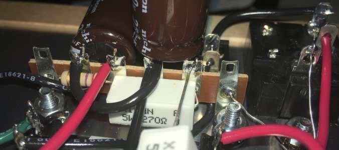
Tapping the tube jostles all the connections in the amp, and a less than perfect connection can be temporarily restored by doing this. Perhaps you could take some new photos since you've reflowed a bunch of joints.
While you are certainly welcome to phone in, any details discussed on the phone will not be present on this thread and will complicate providing future tech support.
While you are certainly welcome to phone in, any details discussed on the phone will not be present on this thread and will complicate providing future tech support.
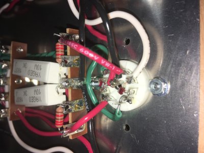
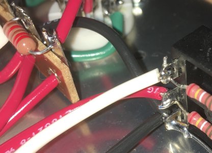
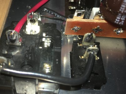
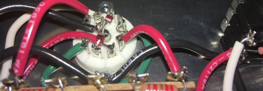
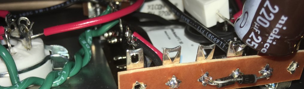
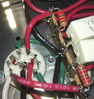
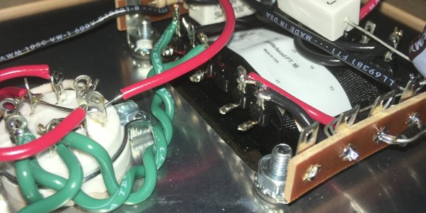
The 22.1K resistor at 5U is not well soldered or connected, though that is a left channel component.
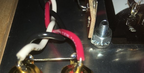
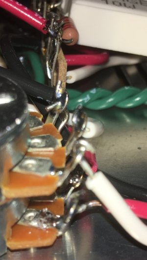
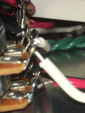
If you wiggle the wire at A5, does it move in that joint?
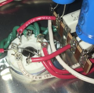
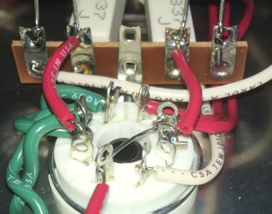
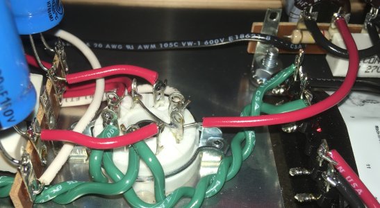
The image of the octal socket is out of focus, so it's tough to say much about that.
-PB
If you wiggle the wire at A5, does it move in that joint?
The image of the octal socket is out of focus, so it's tough to say much about that.
-PB
You may need to shrink the size down a little bit.
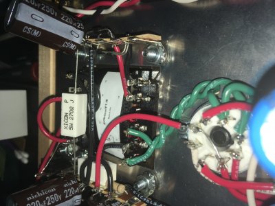
One thing I haven't mentioned is that there was a small chip on the transformer when I received the kit. I took pics and emailed Bottlehead immediately and was told it shouldn't be a problem. Is it possible the transformer was dropped and is damaged? And that's why I'm having these issues?
Attachments
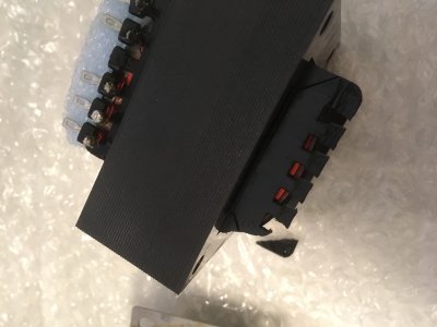
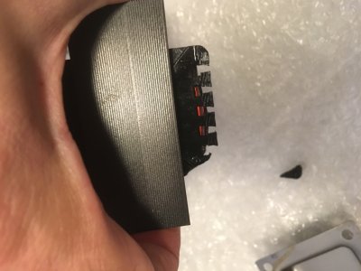
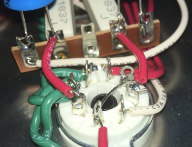
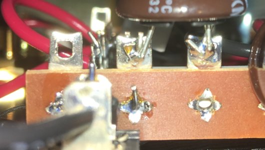
The transformer is definitely not an issue. That little piece of the bobbin that snapped off doesn't serve any function.
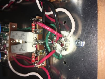
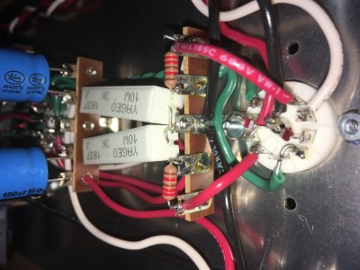
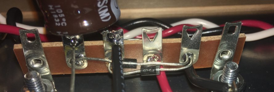
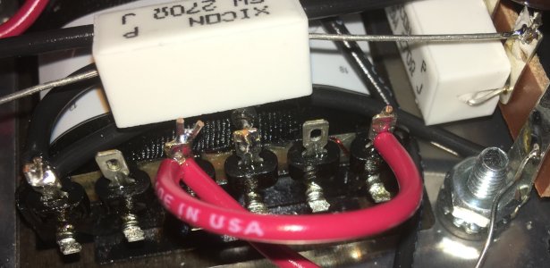
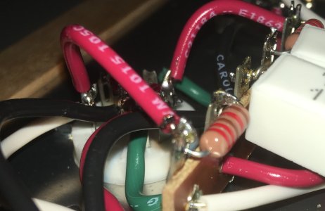
The joints that pop out at me are 6U and the 3K resistors attachment point at 3U. I see a lot of flux at 3U and it's possible that one is really well soldered and the other is somewhat insulated by flux.
The joints that pop out at me are 6U and the 3K resistors attachment point at 3U. I see a lot of flux at 3U and it's possible that one is really well soldered and the other is somewhat insulated by flux.
Paul Birkeland said:The transformer is definitely not an issue. That little piece of the bobbin that snapped off doesn't serve any function.
The joints that pop out at me are 6U and the 3K resistors attachment point at 3U. I see a lot of flux at 3U and it's possible that one is really well soldered and the other is somewhat insulated by flux.
Went over those. No difference. I give up. Will send it in.
Ok fine I guess I haven't given up. Spoke to to Doc B on the phone and ended up cleaning both the tube pins and sockets. Also tried a cheater plug to lift ground. Tiny improvements but still not enough.
One thing dawned on me - the PT had some sort of resin on the contacts. I basically just poked holes in it to slide the wires through and then soldered. Is there any benefit to undoing all PT wiring, making sure the contacts are completely clear of the "resin" and re-soldering?
One thing dawned on me - the PT had some sort of resin on the contacts. I basically just poked holes in it to slide the wires through and then soldered. Is there any benefit to undoing all PT wiring, making sure the contacts are completely clear of the "resin" and re-soldering?
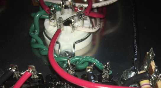
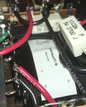
It is varnish, and it should burn right off when you solder. Also, every connection to the power transformer is common to both channels, so an issue here that made noise would make noise in both channels. Such an issue should also rather immediately present itself in the voltage checks.
If you want to check the operation of the transformer, you can measure the AC voltage between pins B7 and B8, then check the AC voltage between pins 18 and 19.
If you want to check the operation of the transformer, you can measure the AC voltage between pins B7 and B8, then check the AC voltage between pins 18 and 19.
Paul Birkeland said:It is varnish, and it should burn right off when you solder. Also, every connection to the power transformer is common to both channels, so an issue here that made noise would make noise in both channels. Such an issue should also rather immediately present itself in the voltage checks.
If you want to check the operation of the transformer, you can measure the AC voltage between pins B7 and B8, then check the AC voltage between pins 18 and 19.
Hmmm ok then that's not it. And voltage checks are a-ok.
Similar threads
- Replies
- 18
- Views
- 480