You are using an out of date browser. It may not display this or other websites correctly.
You should upgrade or use an alternative browser.
You should upgrade or use an alternative browser.
Copper-clad S.E.X. build
- Thread starter JeffYoung
- Start date
JeffYoung
New member
Oops, I was monitoring the bridge, not the transformer.
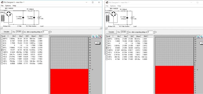
I still get different results, though: 3.1Arms for RC and 3.2Arms for CRC.
The primary difference is that I have the transformer at 223mΩ, whereas you are using 99mΩ.
I measured my primary at 33.3Ω and my secondary at 0.2Ω, which PSUD2 estimates as an effective impedance of 223mΩ. Is yours really as low as 99mΩ?
No load voltage is 6.42V (the photo in the manual has exactly 120V presented to the primary ") ), the rating for the winding is 6.3V/3.5A. I vastly prefer to use these numbers compared to attempting to measure the DCR of a winding with such low DCR. Incidentally, the source impedance actually looks to be a little lower than I posted in that image (I was using the off load voltage from memory, probably from a different transformer).
), the rating for the winding is 6.3V/3.5A. I vastly prefer to use these numbers compared to attempting to measure the DCR of a winding with such low DCR. Incidentally, the source impedance actually looks to be a little lower than I posted in that image (I was using the off load voltage from memory, probably from a different transformer).
I also noticed you went up to 15000uF caps, which drops their impedance a bit also. My load calculation on the transformer with your CRC filter is about 4.3A, with the stock configuration clocking in at 3.6A. (Do note that I have the unfair advantage of having talked to PJ about this in the past)
I've roasted a few power transformers, including one PT-7 (old SEX transformer) last week, and it's certainly a stinky experience!
), the rating for the winding is 6.3V/3.5A. I vastly prefer to use these numbers compared to attempting to measure the DCR of a winding with such low DCR. Incidentally, the source impedance actually looks to be a little lower than I posted in that image (I was using the off load voltage from memory, probably from a different transformer).I also noticed you went up to 15000uF caps, which drops their impedance a bit also. My load calculation on the transformer with your CRC filter is about 4.3A, with the stock configuration clocking in at 3.6A. (Do note that I have the unfair advantage of having talked to PJ about this in the past)
I've roasted a few power transformers, including one PT-7 (old SEX transformer) last week, and it's certainly a stinky experience!
JeffYoung
New member
Yep, the transformer numbers definitely make a difference. Using my no-load voltage (6.64V) and the spec'd power rating gives me 97mΩ, which in turn yields 3.4A stock and 3.7A w/CRC.
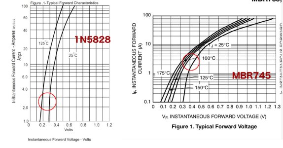
The remaining difference is probably down to the rectifiers we're using in the model. Your 1N5828s have a lower voltage drop than the MBR745s used in the kit.
Here's a reasonably accurate model of the MBR745s if you want to dump it in your PSUD2 rectifiers.txt file:
In any case, sounds like I need to keep an eye on transformer temps. I assume it will get externally warm to the touch before it overheats?
The remaining difference is probably down to the rectifiers we're using in the model. Your 1N5828s have a lower voltage drop than the MBR745s used in the kit.
Here's a reasonably accurate model of the MBR745s if you want to dump it in your PSUD2 rectifiers.txt file:
Code:
MBR745, SS, 0.007, 9, 4000, 45, 150, 7.5In any case, sounds like I need to keep an eye on transformer temps. I assume it will get externally warm to the touch before it overheats?
Attachments
JeffYoung
New member
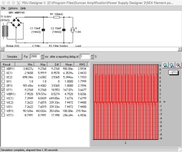
I calculated the ESRs of the two capacitors based on the formula tanδ = 2πfCR and got 20mΩ and 38mΩ at 100Hz. (Not trusting my math I also looked up a bunch of 15,000uF/10V capacitors that did publish ESR specs and they were in the same ballpark.)
Those ESRs (in my model) produce 3.6A CRC and 3.3A stock.
Those ESRs (in my model) produce 3.6A CRC and 3.3A stock.
Oops, I was off by a decimal on the cap impedance (at 120Hz for where I live).
Still the CRC is ill advised.
Still the CRC is ill advised.
JeffYoung
New member
I took some temperature readings running the glow test for 30 min. I used the choke readings as "ambient" to remove any emissivity errors (they're painted with the same black wrinkle-finish paint as the transformer bell).
Temps increased for roughly the first 8 minutes, and were then stable for the next 22. Filament voltage was stable at 6.6V.
There was of course limited drain on the B+ side, so the temps might come up a bit with the whole amp running. The filament voltage will also likely drop a volt or two, which might mitigate the rise to some extent.
Paul's advice is noted, but these seem pretty benign so far....
Temps increased for roughly the first 8 minutes, and were then stable for the next 22. Filament voltage was stable at 6.6V.
Code:
Choke:    ambient
PT-10:    + 3ºC
0R1:      + 19ºC
C-ripple: + 3ºC
C-smooth: + 2ºC
There was of course limited drain on the B+ side, so the temps might come up a bit with the whole amp running. The filament voltage will also likely drop a volt or two, which might mitigate the rise to some extent.
Paul's advice is noted, but these seem pretty benign so far....
Without a load on the HV winding, it will offer a nice, cool layer of copper to sink heat into.
I can offer that when we (mostly PJ, I was just an interested observer) wanted to measure temperature rise in a transformer, we would let it run for 24 hours under its intended load. We (we is again referring to PJ) also would use the change in resistance of a given winding to calculate what the actual internal temperature of the power transformer was at that time with a meter intended to provide accurate DCR measurements at very low values.
There's a huge difference between the temperature of the copper inside the transformer and the temperature of the lamination stack wrapped around it.
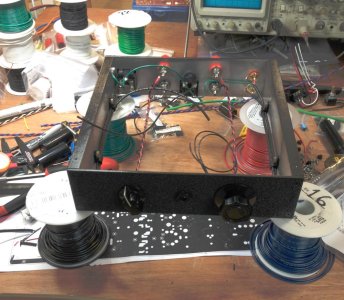

If you left off the 8.2K resistors (it sorta looks like they aren't in there), then the amp will work but may be a little buzzy. This may go away with installation of the C4S upgrade that I see in the background.
JeffYoung
New member
Hi Paul,
I was originally trying to save room on the top lugs for film bypasses on the 22uF caps, so I mounted the 8K2 resistors in-line at the bottom:

Later I concluded that the C4S's would make bypass caps unnecessary so I left them out.
I put the CS resistors on the ends of the flying leads for the C4S boards for now, as my case design will make it difficult to get to them after-the-fact. (I now fully understand the appeal of everything-on-the-top-plate design.)

Cheers,
Jeff.
I was originally trying to save room on the top lugs for film bypasses on the 22uF caps, so I mounted the 8K2 resistors in-line at the bottom:
Later I concluded that the C4S's would make bypass caps unnecessary so I left them out.
I put the CS resistors on the ends of the flying leads for the C4S boards for now, as my case design will make it difficult to get to them after-the-fact. (I now fully understand the appeal of everything-on-the-top-plate design.
)
Cheers,
Jeff.
Ah, nice, you tucked those away nicely.
The top plate design sure does make things easier to build.
A 22uF/450V axial cap will also fit nicely and sit between the two T-strips if you want to complete the look a little more
The top plate design sure does make things easier to build.
A 22uF/450V axial cap will also fit nicely and sit between the two T-strips if you want to complete the look a little more


Similar threads
- Replies
- 1
- Views
- 112
- Replies
- 4
- Views
- 127