How is your supply of clip leads?
You are using an out of date browser. It may not display this or other websites correctly.
You should upgrade or use an alternative browser.
You should upgrade or use an alternative browser.
CAS voltage not the same
- Thread starter bqc
- Start date
I'm thinking that you could remove the secondary wires from both output transformers (just take all of them off, the secondary wires are the jumpers and the twisted pair that heads back to the speaker posts).
Next, recheck your AC voltage measurements. If they are still off, power down the amp, then remove the red and black wires at output transformer terminals 5 and 10 on both transformers. Take a pair of clip leads and clip lead each output transformer into the other channel, then repeat the measurements.
Just as a reminder, the AC voltage measurements should be taken at terminals 5 and 11.
-PB
I finally got around to do this output transformer swap, the left output transformer is wired to the right channel and vice versa, and found that the issues is now reverse. While a 60hz signal is fed to the input, terminal 11 (left channel) AC voltage now is twice the AC voltage of terminal 5. So it looks like the left channel output transformer is bad as wiring it to the right channel cause the AC voltage of the right channel to drop to half of the left channel. So it looks like I need to replace the left channel output transformer. I am also thinking of converting this Stereomour to use type 45 tubes. I read that a 5K primary OT will be a better match to the 45 . In that case what type of OT do you recommend that would fit in the space of the old OT.
Thanks
Thanks
Can you post some photos of your build?
Your first hypothesis was a bad plate choke, and now you've concluded that you have a bad OT.
Could you put things back and take the measurements I requested?
For what it's wroth, we have never had a defective Stereomour output transformer, other than a few that were put in the channel frames upside down about ten years ago. The only plate choke I ever had to replace was due to a wire touching the chassis elsewhere that caused damage to the plate choke.
I'm not aware of a suitable 5K OT that will drop in, but 4K works nicely. 4K is generally not recommended because there are so few 4K output transformer options out there.
Plate choke DC resistances?
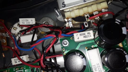
From the photos:
2U looks like it could use a little soldering help.
Terminal 3 on one output transformer looks to possibly not be soldered.
1L looks like it needs some more heat/solder.
The cathode bypass caps mounted above the board won't do you many favors down the road.
2U looks like it could use a little soldering help.
Terminal 3 on one output transformer looks to possibly not be soldered.
1L looks like it needs some more heat/solder.
The cathode bypass caps mounted above the board won't do you many favors down the road.
Left channel. 556 ohms, right channel 553Paul Birkeland said:Plate choke DC resistances?
That demonstrates that the plate chokes are not damaged and don't need to be replaced.
The next step would be to play your 100Hz tone into the amp through both channels. Measure the AC voltage between 5 and 10 on each transformer, then also measure the AC voltage at the speaker binding posts.
I would leave it open.
So with the source at full volume, the AC voltage across 5 and 10 of left transformer is 52V and right transformer is 122 V
AC voltage across speaker terminal left 2 V, right 8 V
BTW I also measure the inductance of the 16 ohm secondary (which is what I am using) Left transformer 0.2 mH , right trans 37mH
AC voltage across speaker terminal left 2 V, right 8 V
BTW I also measure the inductance of the 16 ohm secondary (which is what I am using) Left transformer 0.2 mH , right trans 37mH
Paul Joppa
Moderator
The photos show a wire connected to transformer terminal 6, and none connected to transformer terminal 8. This is not consistent with the 16 ohm wiring. I can't see the rest of the secondary wiring well enough to say more, but the voltage and inductance data suggest a short across a portion of the secondary.
Paul Joppa said:The photos show a wire connected to transformer terminal 6, and none connected to transformer terminal 8. This is not consistent with the 16 ohm wiring. I can't see the rest of the secondary wiring well enough to say more, but the voltage and inductance data suggest a short across a portion of the secondary.
Attachments
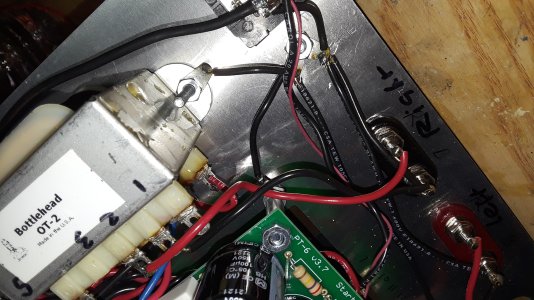
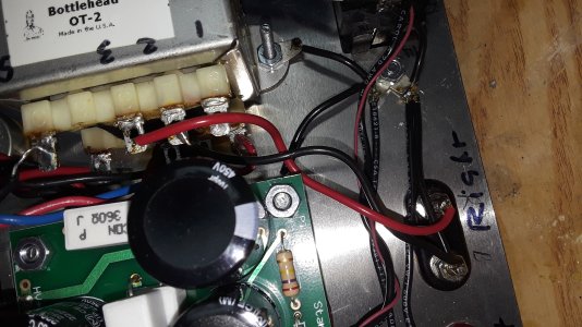
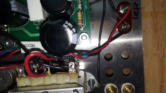
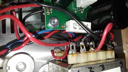
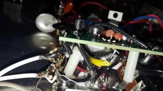
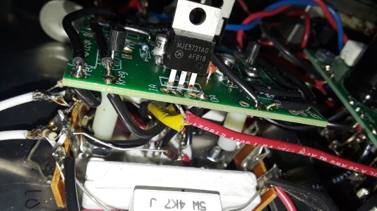
One of your short red output transformer jumpers looks to be touching the chassis.
Similar threads
- Replies
- 3
- Views
- 157
- Replies
- 2
- Views
- 114