Can't get much help on other forums

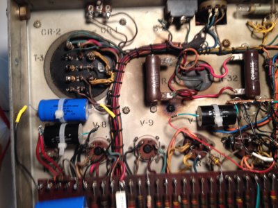
Ok, I am not sure I am hooking up my DVM properly.  I hook my DVM black lead to the chassis then use my red lead to check connections.  I rechecked my C3 capacitor and got 91 VAC on one side and 89 VAC  on the other, not millivolts.  Switching to DC I got 14.5 VDC on one side and -7.5 VDC on the other.  Once again the minute I touch either side on C3 the buzz stops.  But when I test every capacitor connection I get almost the same results with the exception the buzz only stops when I test on C3. I desoldered the C3 capacitor and tested it on my DVM and got the proper reading.  So, I desoldered two other capacitors and they all tested out properly.  Also, there is a meter that tests the two 807 tubes and the VR150 tubes.  The meter registers on the first 807 but not on either the second 807 or the power tubes.  So I have something wired incorrectly I think.   

Per Grainger I rewired the input to a three wire setup and I also shorted the input wires to ground and the buzz was a little less.

My plans are to start checking my rewiring connections and resoldering all the connections to see if I have a bad solder joint.

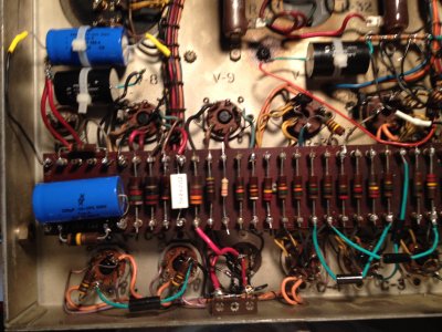
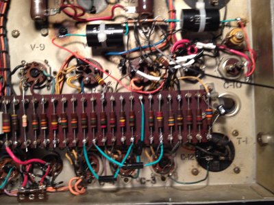
One last question.  This amp is almost 60 years old and one of the resistors, R34, is encased  in a metal case.  The resistor is a 0.2 ohm, 2 watt wirewound type.  It appears to be grounded to the chassis.  Can I replace this with a current equivalent wire wound resistor and ground it to the chassis?

I will say this definitely test one's patience but at the same time it is fun.  I just wish that it wasn't deadly.

Onwards and upwards and once again thanks for all the help.

Richard

 
I would suggest checking the resistance between the chassis and a known power supply ground.  Something just isn't adding up here.

-PB
 
Paul,

This may show my ignorance but are you suggesting I find a power supply ground within the amp.  Would that be a ground associated with the Power Transformer T3.  Also, I see on the schematic a number of System Ground points off the Power Transformer vs Chassis Ground would it be one of these?  Or, there is a black wire on the wiring schematic that is listed as a System Ground.  I currently am using that wire for my negative speaker connection, could I use that to check for the resistance you are suggesting.

This is where I am confused. There is one wire listed on the wiring schematic as Out.  I traced it back to the Output Transformers 8/16/32 ohm taps and am using that for my positive lead (red) to my speaker.  The Common tap, listed as 0, goes through a resistor R34, and a couple of capacitors C9 and C10.  From there a wire shows going out and is listed as the System Ground, I am using that for my negative lead (black) to my speaker.  Am I using the wrong wire for my speaker.  And if so will I have to run a wire from the O tap to my speaker.   

Thanks for the long distance help.

Richard
 
C11 looks to be a multi-section lytic, it should have a single negative lug that is grounded.  Start there, then see where else it goes.  For convenience, you could head to the drug store, grab some green nail polish (should be an interesting checkout process), then dab a green dot where all the grounds are.

-PB
 
Paul,

It actually has two lugs and both of them are showing OL on my DMV.  What am I looking for with regards to a reading. 

One thing on the capacitor.  When I unmounted the old capacitor it had a phenolic plate that went between the capacitor and the chassis body.  The replacement capacitor had a phenolic plate and a metal plate.  Should this capacitor be grounded to the chassis? 

I will look for additional points tomorrow. 

Richard
 
I'd take some photos.

You are looking for the ground leg of your capacitor.  This is power supply negative, and should be ground.  You should have power supply voltage (DC) across this capacitor.  This is the place to start, to be able to actually measure your DC power supply voltage (not AC). 

Once you can measure the power supply voltage, you can leave your black probe where it is and measure other DC voltages in the circuit.

So far, your voltage measurements have been erratic enough that this needs to be nailed down before looking for any issues.

-PB
 
I hope these photos are clear enough. 

Richard


Attachments

  • Upper Left.JPG
    Upper Left.JPG
    683.2 KB · Views: 158
  • Lower Left.JPG
    Lower Left.JPG
    2.2 MB · Views: 161
  • Upper Right.JPG
    Upper Right.JPG
    2.1 MB · Views: 144
  • Lower Right.JPG
    Lower Right.JPG
    2.2 MB · Views: 140
Paul,

A little confused on what you are saying. 

When I look at the C11 capacitor there are three sections A, B, C, plus three lugs on the outer part of the capacitor can.  Are these the power supply negatives you are referring to.  Of the three only two are being used, one between A & B and one between A & C. 

When I trace the wires from these two lugs there are three wires attached.  The wire from the AB lug goes to the C8 capacitor, a second wire goes from the AC lug to the C10 capacitor, and a third wire goes from the AC lug to the V6 voltage regulator tube. 

So am I measuring DC voltage here.  If so am I leaving my black probe attached to the chassis and measuring these points or am I attaching my black probe to these points and measuring somewhere else?

I have been reading but I am still very confused on what a System Ground is.  Sorry for the ignorance and I appreciate your patience.  I hope you don't mind being a teacher here. 

Thanks

Richard
 
Start by measuring the DC voltage across the first capacitor in the power supply.  I think you swapped that out for a Solen?
 
Paul,

I was able to take some measurements.  I measured all the Solen replacement capacitors.  I had my black probe attached to the Chassis and used my red probe on each capacitor.

C8 - two red wires that are attached to R33 & R22 and one black wire that is attached to the ground lug on C!!.  The readings were; on the red wire it started at 18.4 VDC and dropped to and stabilized at 14.3 VDC.  On the black wire it started at -2.18 VDC and dropped to -1.37 VDC.

C9 - two red wires that are attached to C10 and T2 and the black wire attached to R4 and a bridge connection to C10.  The readings were on the red wires; start at 40.4 VDC drops to 19.9 VDC.  On the black wire starts at -3.06 VDC and drops to -1.35 VDC. 

C10 - two red wires attached to C9 & L1 and the black wire connected to R34 and the same bridge connection that C9 .  The readings were on the red wires start at 30.86 VDC dropping to 22.45 VDC.  On the black wire starts at -2.96 VDC dropping to -1.82 VDC. 

Richard
 
Paul,

To make sure when you say across the capacitor  I am assumiung you mean to put my black probe on one side of the capacitor and the red probe on the other. 

If so I got the following readings.  C8 - 487.8 VDC, C9 - 585.4 VDC and C10 -584.8 VDC. 

Richard
 
OK, that is more like it.

The chassis of your amplifier isn't grounded, this is a problem.

I'm guessing you don't have a 3-wire power cord on the amp?

This is a safety issue to address immediately.

-PB
 
Paul,

You are right.  It is an old two prong.  Where would I attach the ground wire in the amp for a three prong power cord. 

When I look at my old BH Seduction the IEC connectors ground terminal goes to the chassis and also to the transformer.  So would I run a wire from both the chassis and the transformer.  If so, I think I know how to ground the chassis, but looking at the transformer I do not know what point to use as ground. 

But I do have a question.  If a capacitor is supposed to block DC voltage why am I getting readings showing DC voltage. 

Richard
 
rockpassion said:
You are right.  It is an old two prong.  Where would I attach the ground wire in the amp for a three prong power cord. 

When I look at my old BH Seduction the IEC connectors ground terminal goes to the chassis and also to the transformer.  So would I run a wire from both the chassis and the transformer.  If so, I think I know how to ground the chassis, but looking at the transformer I do not know what point to use as ground. 
Yeah, the Seduction is a good model to follow.  You probably have 2 prongs coming in, and one of the prong is soldered to the chassis (bad).  You want to add a 3 prong cord.  Hot and neutral go to the power transformer primary (through switch/fuse, add a fuse if there isn't one), the earth connection goes to the chassis at the closest possible place from where it enters the amp.
rockpassion said:
But I do have a question.  If a capacitor is supposed to block DC voltage why am I getting readings showing DC voltage. 
Capacitors store charge (good for a power supply), and offer a reactive impedance to AC (also good for a power supply, power supply noise is shunted through the cap to ground).

The DC blocking application works for coupling capacitors, where the cap offers relatively low AC impedance while blocking DC voltage from the next stage. 

-PB
 
Paul,

Thanks!!!  I checked the schematic and traced the 115 VAC wires  to both the on/off switch and the fuse directly, one wire to each.  By what you are saying I am going to find a point close to where the ground wire from the 3 prong cord originates into the chassis and connect it directly to the chassis. 

I might not do that today but as soon as I do should I measure the same capacitors in the same way again? 

By the way,  I think I have learned more in the last 30 days than in the previous 5 years of just constructing the kits.  This is great.  I love this forum!!!

Richard
 
Yeah, you really want to nail down the whole power cord thing before doing anything else, I should've brought it up earlier.

You should find that one of the wires from the 2-prong cord connects to the chassis somewhere.  It's also possible that they just come in and go to the primary, and that the chassis is floating (gasp!).

Once you have the power cord properly installed, then you can try measuring that cap voltage again.  If you get something funky, you will want to connect power supply ground to the chassis as well.  (I like doing this close to the RCA jacks or where the signal comes in to the first tube)

-PB
 
Paul,

These amps do not have a power cord.  There are two wires that come from the power switch and one from the fuse.  I attached a three prong cord with the ground attached to a screw on the chassis. 

I rechecked the voltage on the three Solen capacitors and found the voltages very close to the previous readings.  There were as follows.  C8 First reading 487.5 VDC second 486.3 VDC, C9 first reading 585.4 VDC second reading 583.6 VDC, C10 first reading 584.8 VDC second reading 583.3 VDC.

Another interesting thing is, there is a meter on the front that measures  the two 807's and the OD3/VR150's and shows whether they are good or bad.  It registers for the first 807 that it is good  but the second 807 and the OD3/VR150's does not even register.  I have a few 807's and will try them along with another pair of OD3/VR150's.

I Look forward  to your response.

Richard
 
OK, it's good that the chassis is grounded.  I would recommend also grounding the power supply to the chassis.  This is often best done up where the RCA input jacks are. 

-PB
 
Back
Top