Bottlehead crack resistance is wacky?

kong288

New member
Ground: Chassis

Terminal Resistance
1 670 and rising
2 836 and rising
3 0 (0)
4 1000 and rising
5 1158 and rising
6 151 and rising (2.4K ohms)
7 3 (2.9K)
8 0 (0)
9 3 (2.9K)
10 200 and rising (2.4K) ohms
12 200 and rising (0) ohms
13 260 and rising * will climb slowly toward 270K ohms
14 270 and rising (0)
20 330 (0) ohms
22 0 (0) ohms
B3 3 (2.9K)
B6 3 (2.9K)

Am I read these wrong or am I really bad at this??
 
Could be a meter issue, is it autoranging, what is the make/model?

The fact that you have terminals that should be grounded showing up with values is troubling. Can you post some pics of your build?
 
I bought it today. It's a GE2524. I'm using the black in COM, the red in VQmA. Settings are on 2000k ohms.

Here are some pictures for you:
http://imgur.com/a/RRv9y

Do you mean it just keeps going up? Because I think so. I don't see any wires touching others that shouldn't. So I don't really understand.
 
What I meant was that you have terminals that should read 0, but do not read 0. That is a major red flag in a resistance check.

The problems are not meter related (although when you go back to do your measurements, you should not exclusively use the highest range; you will get more accurate measurements using lower ranges when you can).

Your solder joints have too much solder. Generally speaking, you have balls of solder on your joints. The ideal is to have a strong mechanical connection and just enough solder to keep everything in place. This can cause all kinds of havoc, between not having an electrical connection, or creating electrical connections where there shouldn't be connections (i.e. the solder bridging the hot and ground of your RCA jacks).

The other problem I can see is misplaced components. You have a capacitor at 11L and 12L. It is supposed to be at 12U and 13U. You don't have nuts securing your transformer. The 270Ω resistor that should be on the inside of the terminal strip is on the outside of the terminal strip. Most of your leads are much longer than what is shown in the manual; this can be a problem because it leaves components free to move around and short out against other terminals. Once you have fixed your issues, you may experience noise in the completed amplifier from not having twisted heater wiring and braided input wiring. These are a few examples, not a complete list. Overall you need to go back though the manual step by step. Carefully re-read the sections about how to solder, many people find watching videos online can help their technique. Above all, confirm that all components and wires are attached to the terminals shown and described.
 
Is there any way I can use my volt meter to see if specific parts are working?

Is the nuts not being there a problem? And the resistor being on the outside doesn't matter if it's the same connection, right?
 
The point of the resistance checks is to see whether certain sections of the amp have been correctly constructed. This is the first step in using your volt meter to see if specific parts are working. If all your resistance check out, the amp may be safe to switch on. By looking at the different resistances, the Bottlehead crew will be able to guide you to the problem areas. Right now you have several things that need to be fixed, and Josh has pointed out those that he could see. You will need to compare your build to the manual step-by-step.

Take your time while fixing these issues. There is no need to rush. Triple-check each connection before you solder. You should find that soldering has become a little easier by now. Trust me, the experience you gain in fixing your issues will definitely give you added confidence for any future builds.
 
thanks for all the suggestions! I followed them all.

1 *
2 *
3 0 0 ohms
4 *
5 *
6 2.48k 2.4K ohms
7 2.92 2.9K ohms
8 0 0 ohms
9 2.93 2.9K ohms
10 2.47 2.4K ohms
12 0 0 ohms
13 1? random goes to 20 then back to 1. maybe out of range?* will climb slowly toward 270K ohms
14 0 0 ohms
20 0 0 ohms
22 0 0 ohms
B3 2.92 2.9K ohms
B6 2.92 2.9K ohms
RCA jacks:
Ground lug 0 0 ohms
Center pin 93k90K ohms—100K ohms

I guess i'm ready for the next step..!
 
Your resistance checks look a lot better now.

Regarding terminal 13, I don't have my Crack in front of me, but I do believe there is a capacitor on there. Not sure if this is the case, but I believe it should climb to 270k ohms as the capacitor gets charged. If you don't maintain constant contact, then the resistor will drain the capacitor and your reading will go back down. I would suggest using alligator clips with your voltmeter here. Alligator clips also make your voltage checks a lot easier / safer, so I would recommend getting some. I used a kit like this with my voltmeter http://www.amazon.de/gp/product/B00CL825ZW/ref=oh_aui_detailpage_o01_s00?ie=UTF8&psc=1

If I am wrong on the above, I hope Josh will correct me.
 
I have a question. I followed the next step by putting in the tubes, the fuse, and plugging it in. But for some reason the tube doesn't turn on. Also, as far as I can see, the fuse isn't blown. I really don't see any wires touching others it shouldn't.. But is there any other way to check the source of my problem?
 
If your resistances measure correctly, then your resistors should be in the right spots and the circuit is correctly built. That does not mean that your capacitors, rectifiers and diodes (LEDs) are aligned correctly. I would recheck the alignment of all of the caps, rectifiers and diodes. Could you report back on those?

However, I know just enough to be dangerous, so if all of those items are aligned correctly, then Josh will need to help you further

From what I have read on the forums, a common problem appears to be with the diodes on the 9-pin socket. Those can be damaged easily, and would cause the tubes not to light up.
 
On the resistances, when I put my meter on 200 ohms (the lowest), the 13th is 2.0. Isn't it supposed to be A LOT higher than 2.0?

Also, does it matter if the leds are damaged? Don't they just assist you on finding out what's wrong?
 
My voltmeter shows 1.0 when the resistance is above its set threshold. If you set it to 200 ohms, it won't be able to measure the resistance accurately. You need to use something above 270kOhm for the meter to give you the correct reading.

I believe the LEDs help with regulating the voltage. If those are damaged, they can't perform their function.

I forgot to mention, but you also need to ensure that the 8- and 9-pin sockets are correctly wired. Any mistakes there, and the tubes most likely won't light up. Also, I don't think the resistance checks will detect any mistakes there.
 
The nuts are there to secure the transformer. Loose transformers vibrate, creating noise, and the grounding of the transformer is based on having a strong physical connection. If you ever ship your amplifier, you run the risk of having the transformer break free, quite possibly completely trashing your amp. Every part included in the kit is there for a reason, every step in the manual is there for a reason. It could be a matter of safety, or audio performance, or just to make a functional circuit.

You asked about the LEDs. They are there to bias the tube so it functions, they are not indicator lights. It is unclear from your pictures if they are oriented correctly or not. The stripe MUST be connected to the center pin of the socket. Also when I looked that picture to check, I noticed that the potentiometer is miswired. Did you already clear that up?

Your resistance checks are looking much better now. As for term 13, your meter will try to charge the capacitor, but it will also see the 270KΩ resistor. What a meter will show under these connections will vary from type to type. It will not be able to read the resistor when you have it set in a lower range. You would not be able to read that resistor with one probe on each lead on any setting other than 2000KΩ.

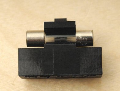
You can check your fuse to see if it is blown by setting your meter to the lowest resistance range and putting one probe on each end. You should read less than 1Ω if the fuse is good. Also a common mistake is to put the fuse in the portion of the holder meant to keep a spare fuse, rather than the part that actually puts it into use. See the pic attached.

I am unclear on what your last question means. Page 36 shows the completed Crack.


Attachments

  • fuse.jpg
    fuse.jpg
    73.3 KB · Views: 152
In addition to the miss wire on the potentiometer there is also a black ground wire missing from the potentiometer to 3L page 22 of the manual, posting a few more pics of where you have got to in chasing down the areas that need attention would be helpful.

Some close ups and different angles of the tube sockets, rectifier diodes, rca sockets and headphone out sockets would be a good idea before thinking about plugging in. 
 
This might be a case where it's just best to purchase a fresh set of hardware and electronics from us. 

Very little in your build resembles what's in the manual in terms of layout, placement, lead lengths, and soldering.  Consequently, when looking at your build for where the problem might be, it just ends up looking like it's everywhere. 

We haven't seen the wiring around the 8 pin socket, but I would suspect that the keyway is not facing the front of the chassis.

-PB
 
Don't plug that amp in yet. For one thing you have a white rectangular 270 ohm resistor across the top of the power tranformer that is dangerously close to touching the transformer terminal that is connected to AC mains neutral. Also I think your filter capacitor and the other 270 ohm resistor are not soldered at terminal 15. Also, your RCA jacks look they they are shorted between the center pin and the outer shell, with solder. They will need to be reheated enough to get the solder from the center pin so it doesn't touch the outer shell/threads. You can use solder wick or a solder pump for that.

All of the excess leads need to be trimmed, and several of the solder joints look like they need more heat to properly flow the solder into the joint. Getting it to look more like the pictures in the manual will be worthwhile. If you go back over each terminal strip, straightening the wire dress, reheating any blobby looking joints and making sure things that shouldn't touch are properly separated you should have an easier time of getting it up and running. I will also suggest that you give us some photos of the areas that we can't see in the images you have posted so far.
 
I rotated the place where the big tube goes so it's pointing in the right direction, resoldered, and tried to take as much solder as I could. I moved the 270 ohm away from the a/c wire. And I do have the black cable coming from center to L3. Here's some closer pictures:

http://imgur.com/a/szTAx

To be honest to me it does look like the end product. I really don't think I need to buy it from you again. At least in the Manuel I'm using. There is a lot of solder, however. But i've taken a lot off from before.

I also fixed the rca jacks and retested the ohms. They're both grounded right, and their grounds are 0.

While cleaning up the bottom area of the amp I broke an LED. what's the best way to get a new one?

 
Back
Top