Thanks for reviewing my concept circuit. I've not used a C4S as a current-sink before, so I wasn't sure about the connections and where the resistors go. Let me respond to your comments as best I can, and perhaps I'll feel more confident about how the circuit works.
1. You shouldn't need/use two separate filament regulators unless heat is an issue.
Response: Rod Coleman (inventor of Coleman Regulators) advised against running more than one tube per regulator. He says this results in poor sound from mixing of the plate currents.
2. R3 isn't drawn in the right spot.
Response: I wasn't sure how to set up a C4S as a current sink. Where should it go?
3. The resistor above R3 appears to serve no purpose.
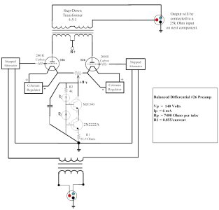
Response: This is a 10-turn, 20 Ohm potentiometer. Its purpose is to allow for minor balancing of the tubes by adjusting their bias. The tubes should be matched, but the pot allows for minor tweaking. If both tubes are perfectly matched this pot would be centered. If one tube is stronger and passing more current I can adjust the bias to favor the other tube. Balancing the currents should improve the performance of the transformer.
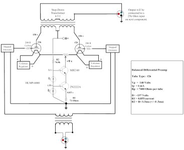
4. R2 could be a 5K resistor and R1 would be about 142 Ohms.]
Response: My schematic has no resistors labeled R1 or R2. Where should these go? (and what is the formula for calculating them?)
I would tie the two filaments together, then use a pair of 10 Ohm resistors to make a virtual center tap, then connect the output of the C4S there. Do note that you may end up needing a hum pot.
Response: A hum-bucking pot would probably require the two filaments to be tied together and be fed by one regulator. This is advised against. Anyway, with this regulator there really shouldn't be any hum. These regulators operate with hum measured in micro-volts.
6. The AC balance provided by the C4S will be exceptional! The DC balance will depend a bit on the tubes themselves, and you may find that transformer performance will improve with matched pairs of tubes.
(and of course, I'd throw in that a single ended circuit with a C4S plate load, parallel feed capacitor, and parallel feed output transformer would be worth building to compare against the differential circuit)
Response: I've got quite a stash of #26 tubes and plan to acquire more.
")
I'm hoping to find a matched quad to within a half-mA or better. I'm sure the tranny will appreciate the effort. And for parafeed? Actually, I've got another design I'm working on using chokes and parafeed out. I still haven't decided which direction I will go. However, both options have a CCS in the tail, so I need to work out this part of the circuit first.
Question: If the Rp of each tube is 7400 Ohms, what is the impedance as seen by the transformer in a balanced/push-pull configuration with a CCS in the tail? Is it just doubled? (i.e. 14,800 Ohms), or are other factors involved? There is no kathode resistor (and no bypass cap). The CCS acts like an almost infinite resistor. However, since each tube is operating in opposite phase there is no voltage change at their joined kathodes. With no voltage change, there is no degeneration, and there should be no multiplication by Mu to affect the plate resistance. At least that is my (crude) understanding.
This is all very tentative in my mind and I'm still reading my books to learn how this works. I'll need to know the impedance in order to narrow my search for an output transformer. If you have a clue on how to determine this, I'm all ears.
Thanks again for all the assistance.