Grainger49
New member
Mike, is that battery on a cathode?
Grainger49 said:Mike, is that battery on a cathode?
Mikey said:Hi Grainger,
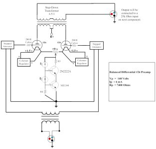
The input stage of this phono preamp is a cascode, and I replaced the bottom
tube (2X 12AT7's in parallel) with a MAT12 transistor. With the transistor in
the circuit, I can use the battery to bias the top tube in the cascode...
Mike
Grainger49 said:Should this be quieter?
Paul Joppa said:In my opinion there is not going to be any noticeable sonic difference; the device is largely controlled by the small transistor. But the tube will be more robust - less chance of blowing something if anything goes wrong - and it will get a heat source up on top and out of the chassis insides, which is always a good thing. Downsides are of course heater power and real estate.
It's not a transistor, it's FET - MOSFET to be specific. It's enhancement more so it needs several volts of positive bias, more than can be supplied by an LED. I don't know to what extend the cascode arrangement will reduce the potential for distortion from the high and nonlinear capacitances. We never experimented with FETs, though I know Tucker and the late John "Buddha" Camille tried several circuits a decade or more ago and rejected them as inferior sounding.Mikey said:...
Could an IRF820 (see attachment) be substituted for the MJE340 without any issues?
It looks like a pretty beefy transistor,...


Paul Joppa said:"Measure ground to the 6SN7 cathode in your case"
Not really. If you bought something like the SEX C4S kit, you could cut the board in half and then substitute an MJE-340 in for the MJE5731A/MJE350, as well as a 2N2222A for the PN2907. The LED's also fit in the other way, and for a current sink, the ground terminal goes to B+, then the "I" pad is the input (ground or negative rail) and the "O" pad goes out to your cathodes.Horns Forever said:Thanks to both of you for the quick reply. I'll likely buy a C4S kit to experiment with. I bought one 10 or 15 years ago, but I know I lost the booklet when we moved and I suspect the parts are somewhat changed since then. Do the current kits include the appropriate parts for a current-sink application?
I didn't consider the possibility that you're using a differential DHT. In that case, my alternative will not work. There's also a third alternative that I credit to PJ (not sure if he came up with it or ran across it elsewhere) where you can add a resistor between ground and the negative output of your power supply. Given that you're drawing constant B+ current, you can use Ohm's Law to drop whatever voltage you like across that resistor. One end of the resistor will be at ground potential, and the other end will provide a negative bias voltage.Horns Forever said:I'm not sure I understood the solution offered by Caucasian Blackplate. Is this sort of like "filament bias" where the extra voltage is consumed in a resistor between filament and ground? (but in this case, consumed by the C4S).
If it helps any, I'm going to use a Coleman Regulator on each filament.
We use essential cookies to make this site work, and optional cookies to enhance your experience.