Bitten by tweak

NightFlight

New member
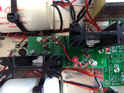
In belief that I have a possible heat issue, I installed ceramic isolators with heatsink compound on the TIP50 transistors... I must have broke the connection somehow on my right channel. The LED's closest to the B+ label there are not lighting up. I've re-flowed the 3 pins on the affected TIP50 to no avail.

Running with just the 6080 only the left channel LEDs light up and Left channel TIP50 produces heat. I see the ~200V on the middle pin of both the right and left channel TIP50's. But I what I don't see on the right side is the lower voltage of ~3V on the other two pins, as seen on the left channel.

Any pointers for isolation?
 
Got the board and TIP50 removed...

Found TIP50 datasheet:
http://www.fairchildsemi.com/ds/TI/TIP50.pdf

Tested the affected TIP50 according to this guide here:
https://www.youtube.com/watch?v=8VK_4gZU__I and it tests fine.

The resistors seem to check out too. Starting to scratch my noodle.  Back to all the voltage checks I guess

 
Completely reflowed the board after having removed and tested the one TIP50.

0V on ground.
0V on the heat sinks
0V on the binding screws

+100V between the 22.1K resistors on both sides.
+200V on the B+
Chassis active side 2N2222A +2.5V
Chassis inactive side 2N2222A +0.16V
Chassis/Collector of inactive TIP50 reads +140V
Active TIP50 shows +122V on the collector/chassis.

Any chance I could have destroyed the 2N2222A with static electricity?
 
Its unfortunate to hear you say that. I guess nothing on the input can lead to the 6080 running pretty hard?

What lead me down the road is random crackling since the speedball upgrade. Starts after couple hours runtime.  Possibly the TIP50's not cooling enough because a fan under the unit resolves the issue. I did try just tightening them down, but that didn't seem to help. So I pulled them back a bit to slip in ceramic isolaters - and the only thermal grease I could come across easily is artic silver. Ironically used for CPU's but is quite conductive. Thought I could be careful enough. I still don't think I shorted the collector to ground.
 
Electrically conductive grease will ruin that board, as it's very difficult to ensure with certainty that it won't move around and short things out.  Arctic Silver, however, appears to not be conductive (according to their website).

Running the amp without a 12AU7 will cause other problems. 

Crackling is generally a flaky solder joint.  Moving air from the fan may have just put enough pressure on it to keep it stable.

It's really important to consider in situations like this that there are a lot of functional Speedballs out there, and we can help you get yours there without so much hassle. 
 
They must have reformulated. Never thought to check their site. The last batch I had was from around 10 years ago or more and I remember being warned about application and potential conductance.
 
I don't doubt the speedball board works and is well thought out, thermal tolerance included. It was just an angle of attack on my part. *shrug*.  Pulling the transistor away from the heatsink might have sonic benefits, so I tried this approach first.

So, what would be your angle of attack? And thanks for the help by the way. 
 
Angle of attack:

Do you have stable voltages at 1, 2, 4, and 5?

Can you run the amp flipped over and look for any LED flickering with the Crackling?  If there's an operational interruption with the crackling, you might be able to see it.

You can also leave the two small boards in and reinstall the 3K resistors, then check operation again.

-PB
 
1.  77V
2. 186V
4. 186V
5. 77V

As for flickering, no. I've not moved back to listening for crackling since the loss of audio in the But I've no audio in the one channel. Crackling is a long term hunt.

The two LEDs are out.


Attachments

  • Photo 2014-06-06 07.09.40 PM.jpg
    Photo 2014-06-06 07.09.40 PM.jpg
    1.8 MB · Views: 161
... some time passes.

I would say we got two birds with one stone. The original heat/crackling problem is gone as well with just the 3K resistors in. Makes sense because the issue only appeared with the addition of the speedball boards.  With time and mods, that point got blurred in my mind. Feels good to have it pinned down.
 
Checked the TIP50's again. My one TIP50 is non functional.  Must have been partially working the other day when I tested it removed from the circuit. Either that or the collector leg is busted internally and requires stress from clamping down to fail. I only say that because the B-E diode test works, just not the B-C. Nothing on the reverse. It be dead.
 
The other transistors and resistors check out on the removed board as well. The only thing I'm not certain about testing are the LEDs.
 
Generally, it's just easier to replace everything if you are going to replace one thing.

I would also highly recommend not using those ceramic insulators.  It would be hard to say if they would conduct enough heat to effectively cool the TIP50. 
 
Most multimeters will have a diode test function which you can use to compare the reading to a known good one, they should also light up during test.
 
The ceramic  insulators are supposed to contain aluminum oxide to overcome the heat conduction issue. The working channel actually got the heatsink very hot very quickly. On par if not better than the pads that come with the kit.  If they insulate the transistor too much - I'll learn the hard way.  ::)

I have to look for a unique angled standoff to get one of the smaller boards installed and stable. Currently its just floating in there and its not good at all.  So I may just order a few Fairchild TIP50 from mouser while I'm at it.  If that doesn't work then I'll ring up the queen and order the whole board.

Paul, can I mix and match with this part?
http://ca.mouser.com/Search/ProductDetail.aspx?R=TIP50virtualkey51210000virtualkey512-TIP50

Not certain where you guys source your parts. Its funny how many other Crack/Speedball parts come up as suggested by others who shop at mouser.

Re LEDs:
I found my meter did not provide enough current/volage to light them up enough to see with the light on. Getting it dark enough in the room prevented probes to be used....

Eventually I figured out I can just use a 9V battery with a 220ohm resistor in series with test leads to light them up properly. Found a bad LED on the bad channel side.  Curiously was an issue with one of the smaller plate boards early on and triggered similar crackling... followed by a gigantic SNAP in the one channel. I have a feeling its the root cause here because its so similar to the previous crackling issue. 

 
Yes, I believe those are the TIP50's we use.

If aluminum oxide is used in those ceramic parts, are they themselves conductive?
 
I just tested first hand with a meter and my skin is more conductive, which initially threw me off.  I took a spare one and wet both sides with a little water to get good conductivity with the part.  It still insulated enough beyond what the meter can pick up.

The datasheet lists the dielectric strength.  The mouser part is 532-4170. And here is the datasheet: http://www.aavid.com/product-group/interface/insulators (TO-220 form factor).


Back
Top