Bigby - My Big BeePre Rebuild

  • Thread starter Thread starter Deke609
  • Start date Start date
I tested the interaction between filament transformers for myself today by powering one fil trafo and listening with the scope to the primary of the unpowered other. Results attached. Best: spaced with center lines of coils at 90 deg and not crossing - about 2mV.  Worst: stacked on top of each other - about 160mV.  Note: in the scope shots, the purple trace is the induced signal on the second trafo. The scope shots are taken at different scales to make the traces equally visible: 500 mV per vertical division for the worst, 100 mV for 2nd worst, 50 mV for third worst, and 20 mV per division for the 3 best.

I also tried looking for interaction when both were powered, but couldn't detect anything.

cheers, Derek
 

Attachments

  • transformer interaction results.png
    transformer interaction results.png
    2.9 MB · Views: 35
I think you're completely missing the point. 

What would the negative consequence be of having your power transformers all aligned? 

How about your filter chokes aligned with your power transformers? 

What would the positive consequences be of having your power transformers and chokes all aligned?

 
Paul Birkeland said:
I think you're completely missing the point. 

Sheesh. My point was to see for myself how coils interact!

What would the negative consequence be of having your power transformers all aligned?

Speculating: could be bad news for any wiring/components between them.

How about your filter chokes aligned with your power transformers? 

I don't want a final filter choke aligned with a PT - no sense in going to the trouble of adding a CLC or CLCLC filter to remove ripple, only to have some ripple put back in the power supply via magnetically induced current in a choke (even if it's tiny, the idea of it offends me  ;D  )

What would the positive consequences be of having your power transformers and chokes all aligned?

Can't think of any that involve the chokes also being aligned.  What are the positives of this?

cheers and thanks, Derek

 
For learning purposes, you could also check the AC current induced in the unpowered coil, and calculate the impedance of the equivalent source. That would tell you how much effect it would have in a real circuit, or at least the things you would need to do that.
 
Deke609 said:
Speculating: could be bad news for any wiring/components between them.
I would put this under the category of being a more likely issue when you have magnetic fields directed in many different directions (IE coils not aligned)
Deke609 said:
I don't want a final filter choke aligned with a PT - no sense in going to the trouble of adding a CLC or CLCLC filter to remove ripple, only to have some ripple put back in the power supply via magnetically induced current in a choke (even if it's tiny, the idea of it offends me  ;D  )
Who is to say that it will be in phase with the power supply ripple.  What if the interaction partially cancels some of the ripple.
I would put this under the category of being a more likely issue when you have magnetic fields directed in many different directions (IE coils not aligned)
Deke609 said:
Can't think of any that involve the chokes also being aligned.  What are the positives of this?
With everything aligned on the power transformer, you are taking advantage of the fact that we have built and evaluated the BeePre under very similar conditions, and you're improving your odds of not running into issues.  If you start firing magnetic fields in new directions, then you are giving up on that.  I would also mention that the grid of a 300B is technically a vertically aligned coil.
 
Many thanks again PB. I appreciate your patience - I *may* finally be getting it!

Paul Birkeland said:
Who is to say that it will be in phase with the power supply ripple.  What if the interaction partially cancels some of the ripple.

The possibility of cancellation may explain why I found that minute adjustments to a "noisy" configuration could make the interaction disappear, but nudge one trafo every so slightly and the noise/interaction reappeared.  I briefly thought of installing the PTs and chokes on plates with a single central mounting bolt and rotating the PT/chokes to find the least noisy position before tightening things down - that's still a possibility for the final build on the metal chassis.

With everything aligned on the power transformer, you are taking advantage of the fact that we have built and evaluated the BeePre under very similar conditions, and you're improving your odds of not running into issues.  If you start firing magnetic fields in new directions, then you are giving up on that.  I would also mention that the grid of a 300B is technically a vertically aligned coil.

I think I finally see your point. I don't need to worry about the interaction between power supply coils: provided the PTs are mounted in phase they are operating with and producing the same 60 Hz sine wave; and the interaction of 60Hz interference with rectified 120 Hz ripple would only slightly augment the ripple waveform (partially cancelling one hump and boosting the next). So my new plan is is to have all four PTs (two stock plus 2 new filament) and the two first HV filter chokes  aligned in a row along the long edge of the chassis, and the remaining final chokes (2 for HV, 2 for LV) aligned in an adjacent row. The alignment will have the center lines of all coils running parallel with the long side of the chassis and away from the 300Bs.  I can space the final chokes at least 5-6 inches way from each other (center to center) - based on yesterday's experiments I know that that yields decent results.

cheers, Derek

[Edit - Oh shoot. Regarding in phase or out of phase - I may need to read up on this. I recall something about time constants with caps and inductors, with voltage either leading or lagging current depending on impedance/capacitance?  In which case different cap/inductance values will produce different phases? No need to correct if I'm wrong - I'll read up about this tonight]
 
My Beepre lives and hums again!  :)  >:(

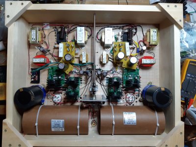
The hum is quieter but still there. But the real kicker is the wood frame adds 1 and 1/2 inches of extra width and length over the metal chassis that I spec'ed to fit my rack. So [the prototype] doesn't fit, and I can't listen to it in my main system.  That is very disappointing.  Not sure how i am going to solve this one.  [Even without hum, I am at least a month away from doing the final build in the slightly smaller metal chassis] The Beepre has been out of commission since August, and I've not enjoyed listening without it. So I'm jonesing to listen to music through it again - even with a bit of hum.

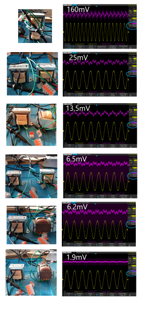
Re hum troubleshooting -- The B+ is about 20V high, so I will fix that today. I have no idea whether that could contribute to hum (e.g., by overworking the EL84 shunt reg), but it needs to be fixed in any event.  I haven't yet mounted the transformers/chokes on L-brackets to get their cores perpendicular, so I can try that too. And if that doesn't do it, there's still a couple of grounding paths that I can play around with.

My best guess is that the hum is coupled onto the plate voltage supply. The signal wiring is well away from the magnetics, so I don't think that's were the hum is getting in.

On the upside: mounting the BeeQuiet internally on a L-bracket worked well, and I'm now so familiar with the BP circuit that I could probably draw the schematic with the right component values from memory (other than the solid state bits)!

Worst case scenario: I will rebuild it stock in the larger chassis that will accommodate the gigantic 10uF copper foil caps.  But I'm still a long way off from giving up.

cheers, Derek

[bracketed edits added to clarify that the wood build is just a prototype, but I wanted to listen to it for the month or so it will take me to complete the metal work on the final build]]
 

Attachments

  • Bigby prototype 1_hums.jpg
    Bigby prototype 1_hums.jpg
    322.5 KB · Views: 32
Question for PJ or PB: the schematic shows B+ of 180V, but the voltage checkout calls for 186V - which should I shoot for, or does anything between these two values work?

many thanks in advance, Derek
 
The schematic shows the design expectation, before thy example was built. The voltage check shows what was actually measured on the production prototype. Neither is critical; the usual +/-10% is applicable.
 
Paul Joppa said:
The schematic shows the design expectation, before thy example was built. The voltage check shows what was actually measured on the production prototype. Neither is critical; the usual +/-10% is applicable.

Many thanks PJ. I knocked it down from 200V to 189V, which based on your above advisement means it is close enough.

cheers, Derek
 
Well, this is really strange. I wanted to take a break from working on the amp and finally listen to it, so I figured out a way to get in my rack and fired it up: almost no hum. But that's not the weird part. The weird part is that it seems like the hum is coming from me! If I just put my hand near the attenuators, but without touching them, the hum get louder. And when I do that, I can hear what sounds like a helicopter: ticka-ticka-ticka-ticka-ticka. It gets a bit louder still if I touch the knobs.

Another thing that's changed: I forgot to power everything through the variac. So everything is running off of mains which is probably 115VAC. I'll hook up the variac and test tomorrow.  Right now I'm enjoying listening. Life is good.

cheers, Derek
 
The prototype is all wood, including the chassis plate which is 1/4 ply.  So I'm stumped.  But it sounds great so I'm pretty happy for now.
 
Then every piece of metal that would otherwise touch a metal chassis plate needs to be wired together with a separate ground that will act as a chassis ground. 

A wood top plate is definitely a high risk for additional noise.
 
Paul Birkeland said:
A wood top plate is definitely a high risk for additional noise.

Thanks PB. That heartens me. Maybe the final build in the metal chassis will quiet things down even more.
 
Well, Santa must have some audio elves, because the hum is now only faintly detectable with the attenuators fully open. If I wasn't listening for it, I wouldn't notice it. Super pleased!
;D
 
Back
Top