Bigby - My Big BeePre Rebuild

  • Thread starter Thread starter Deke609
  • Start date Start date
D

Deke609

Guest
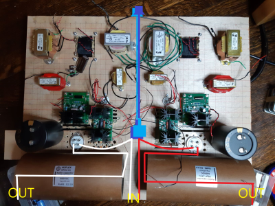
Here's my first stab at the layout of my BeePre rebuild.  Does anyone see any howlers?

The gigantic caps are 10uF 600V copper foils that I originally intended to install in the Kaiju - but they were too big, even with the planned bigger chassis.  The 600V is about 500V more than I need, but I can't find a 10uF 100-250V copper foil cap that isn't min $1K for a pair.  These cost me half that on sale. So in they go! 

cheers and thanks, Derek
 

Attachments

  • BigBee knock up.jpg
    BigBee knock up.jpg
    326.1 KB · Views: 138
With everything else being symmetrical, are lower middle transformer pairs at right angles to each other for electromagnetic field reasons? Asking as someone who knows virtually nothing about such things!
 
Deluk said:
With everything else being symmetrical, are lower middle transformer pairs at right angles to each other for electromagnetic field reasons? Asking as someone who knows virtually nothing about such things!

Hi Deluk - that's the idea.  Some other configuration might be better, but I'm just following the rule of thumb that coils turned 90 deg to each other are less likely to magnetically couple and generate hum.  All trafos and chokes will also have flux bands wired to ground that are made up of 3 layers: 30 awg copper sheet, a mumetal-like film called MCF5 that can be cut and bent, and then thin copper adhesive tape to hold the layers together.  The manufacturer of the MCF5 states that it results in -30dB attenuation from 10Hz to 200kHz. But it's so thin, I figure it must saturate really quickly - but I'm hoping the connection to ground takes cares of that.  But based on what I've read, the prevailing wisdom seems to be that shielding offers fairly minimal benefits, with spacing and orientation of magnetic parts being the best way of minimizing magnetically induced hum. But don;t quote me ... this is just my recollection of stuff I've read. I don't understand the science of it.

cheers, Derek
 
Deke609 said:
Hi Deluk - that's the idea.  Some other configuration might be better, but I'm just following the rule of thumb that coils turned 90 deg to each other are less likely to magnetically couple and generate hum.
Those coils are both pointing straight up, they are aligned.  As far as magnetic coupling goes, that's for an emitter (power transformers) and a receiver (signal carrying transformer).  There are no signal transformers in the BeePre.

You can also create some problems with high gain circuits picking this stuff up, but this shouldn't happen in the BeePre.
 
Paul Birkeland said:
Those coils are both pointing straight up, they are aligned.

In a bad way? I could make some aluminum L-brackets for mounting alternating chokes/trafos so that the center-line of the coils are at right angles.

cheers and thanks, Derek
 
Paul Birkeland said:
I don't know, you'll have to do the experiment and see.

Well, I have a penchant for over-complicating things that I don't understand ... so why not?    L-brackets are now part of the plan.  ;D
 
Hi there,

I'm curious - what are all the various transformers (chokes, I presume) doing in there? I do recall there being an opportunity to sub in a couple of small chokes for 300 Ohm resistors, but how about the rest?

Where will the input/output jacks, switches, and input output wiring be accommodated? In the stock BeePre, those seem to occupy some space along the front and rear edges of the layout.

Those caps are impressive!
 
caffeinator said:
I'm curious - what are all the various transformers (chokes, I presume) doing in there? I do recall there being an opportunity to sub in a couple of small chokes for 300 Ohm resistors, but how about the rest?

Where will the input/output jacks, switches, and input output wiring be accommodated? In the stock BeePre, those seem to occupy some space along the front and rear edges of the layout.

The two larger silvery ones between the power trafos are dedicated filament heater transformers for the 300Bs. I'm using EML 300Bs that draw 1.3A instead of a regular 1.2A.  The additional current dropped the voltage output of the stock heater windings a bit, and that combined with my wacky mains voltage over the summer was causing the LM1085 filament regulators to "drop out", resulting in hum. Plus, I wasn't able to hit my target of 4.9V dropped across the filaments - which would be within 2% of the ideal 5V.  The new filament trafos get me there.  All the others are chokes as you figured. There's a CLCLC filter for the HV and a CLC for 300B filament heater circuit.  Prompted by Deluk's question and PB's input, I'll be mounting half of them on L-brackets to get the coils oriented at 90 deg to each other (I based the current setup on on the typical way of orienting top-mounted PTs and OTs - forgetting that the center lines of their coils run parallel to the chassis, whereas my chokes are all perpendicular to it -- thanks Deluk and PB!  :)  )

I'll only be using one source, so I've eliminated the source selector switch.  Volume pots will be mounted vertically in the open space between the 300B sockets with extenders running to the front panel as shown in the attached. They'll be installed on a wider but shorter piece of aluminum sheet  so that the pots are closer together. It's going to be weird looking: PTs in front and tubes in back - but I like the idea of keeping the signal wiring well away from the magnetic bits.  Inputs are at the rear panel between the giant caps and outputs at the outer corners of same.

cheers, Derek
 

Attachments

  • BigBee knock up.png
    BigBee knock up.png
    2.7 MB · Views: 67
Paul Birkeland said:
Personally, I would align all the coils with the power transformers, but that will be difficult.

Many thanks PB - these kind of pointers are really helpful.  Do you mean: align all coils so that their center lines are parallel with the top plate (like the PTs), and then orient them at 90 deg to each other? 

cheers and thanks, Derek
 
Thanks PB.

But I still don't get it - sorry. Do you mean all in a single row? If yes, then also mount them vertically so that their coil center lines are parallel with those of the PTs, or just leave the coils standing upright?

many thanks, Derek
 
No, I mean all the coils pointing in the same direction.  The power transformers now point in the same direction.  I would suggest making all the other power iron also point in that direction.
 
Hi there,

Thank you for the thoughtful and detailed (with illustrations, no less!) answer to my question - looks like an ambitious project!

I think what PB is saying would mean to turn all the transformers, apart from the power transformers, so that their channel frames are parallel to the extension shafts you added to the photo. Then lay them down so that the channel frames would be parallel to the plane of the chassis plate. That would, at least judging from what I can discern as the bobbin orientation in each of them, have them pointing along the same line.

Hope this helps, and good luck with the BigBee!

caffeinator
 
caffeinator said:
I think what PB is saying would mean to turn all the transformers, apart from the power transformers, so that their channel frames are parallel to the extension shafts you added to the photo. Then lay them down so that the channel frames would be parallel to the plane of the chassis plate.

Many thanks caffeinator!  Yes, now I see. That might indeed be difficult. I think I'd have to totally rejig the layout, including chassis orientation - which I will do if I get hum and can't find a solution with the present orientation.

I think for now I'm going to move the filament transformers to where the big chokes currently are, and vice versa. I'm wary of having four power transformers in a row like I do now. And I'll mount all parts so that the center lines of the coils are at least perpendicular.

Question - @PB or anyone else who has played around with using an oscilloscope to test for interaction between inductors (transformers or chokes): to test between adjacent inductors, is it enough to send a signal through the first (e.g., mains power through a loaded PT) and "listen" with the scope to the unpowered second? Or do I need to send a (different) signal through both?

Many thanks, Derek
 
Power up the power transformer, then you can listen to the other coil.  I don't even use a scope for this a lot of the time, a multimeter that can resolve AC mV will usually do the job.

I would suggest doing some reading on the right hand rule and properly aligning coils in a speaker crossover to better prepare you to answer some of these questions on your own. 
 
Many thanks PB.

Paul Birkeland said:
I would suggest doing some reading on the right hand rule and properly aligning coils in a speaker crossover to better prepare you to answer some of these questions on your own.

Yes,  good advice. I was reading about crossover inductor layout last night.  I'll look at the right-hand left-hand rule again - I recall that from the NEETS materials. 

cheers and thanks, Derek

[Edit: wrong hand!]

[Edit 2] I just came across the following helpful link that shows scope shots of the effects of different coil orientations: http://www.audioholics.com/loudspeaker-design/inductor-coil-crosstalk-basics

I should be able to implement the orientation shown in figure 7.
 
Just keep in mind that all of your inductors are carrying 60Hz AC, so crosstalk is completely meaningless.  My suggestion to align all the coils is to avoid spewing that 60Hz magnetic radiation in more directions than is absolutely necessary.
 
Right! Didn't think of that!  I guess this goes back to your original point about interaction with a signal (music) carrying coil like an OT (or a speaker cross-over). Many thanks again PB. That suggests to me that protecting the last filter choke from interference might be worthwhile, but otherwise, I should be ok. But it's probably a good idea for me to take a stab at some minimal approximation of layout "best practice" - so I'll do what I can to keep the magnetics from interacting.  And it'll give me a chance to try out a new 6" metal brake that works with a bench vise.  I bought it and a modestly priced 8" metal shear after seeing the prices that Lundahl wants for transformer enclosures - all in for both, less than the price of 4 enclosures.  And 1/16 steel and aluminum sheet is pretty cheap.

cheers and thanks, Derek
 
Back
Top