Beepre voltage question

Just another observation in case it helps in diagnosing this problem. The voltage at these four terminals in question spikes to 215v when the unit is powered on, then they all settle at 142v within a few seconds.

Also, the issue with the B channel LEDs dimming once the tubes heat up moved to the A channel when I switched tubes. This is still on the "B side" of the C4S board and they are still lit, just faintly.
 
Jamus said:
Just another observation in case it helps in diagnosing this problem. The voltage at these four terminals in question spikes to 215v when the unit is powered on, then they all settle at 142v within a few seconds.
This is the EL84/TL31 regulator powering on and doing its job.

Just out of curiosity, did this BeePre ever work properly?  (I had assumed it did, but I'm realizing that this might be an error)
 
Jamus said:
I got replacement tubes today and rechecked voltages. Now all 4 relevant terminals (2, A2, 17, B2) all measure 121v. This is only 10% over spec (90-110v) so I assume this is okay (?). All other voltages were within spec.

Next I hooked up CD player and BH crack to listen. All sounded great at first, listened for about 5 minutes. I left it playing for about 30 minutes to continue warming up. When I came back to listen there was almost no volume.

I took the BeePre out of the chain and the Crack works fine. I let everything cool down for a few minutes (top plate on BeePre was very hot). When I fired everything back up it sounded normal for about 5 seconds, then volume dropped down again.

Any suggestions on where to start with troubleshooting?

Only for less than 30 minutes  :'(
 
Just going back over the manual step by step looking for any possible errors on my part. On the C4S boards does it matter which 2 out of 3 bB terminal holes are used for black wires?
 
Ah, OK, I should've picked up on that before I had you send off the tubes.  This is almost certainly flaky solder joints in the build, I would just reheat absolutely all of them.  Also be sure that all the heasink hardware is on tightly.

-PB
 
Welp, I just finished reflowing every joint in the entire kit and I still get the same 142v at those 4 terminals. I also went step by step through the manual to be sure I didn't miswire anything. Any other ideas?
 
Jamus said:
Just going back over the manual step by step looking for any possible errors on my part. On the C4S boards does it matter which 2 out of 3 bB terminal holes are used for black wires?

Just want to rule this out as a possible source of the problem. Are there 3 bB terminal holes on the C4S boards and we are using 2 of them or am I misunderstanding the manual on that? If so, does it matter which 2 we use (adjacent holes) or are they all connected anyways?
 
The three bB pads are connected.
Some photos of your build may help, another pair of eyes can often spot a mistake that you missed.
 
Thanks Chris!
My next plan of attack was to poke around with a wood chopstick while measuring DC volts at the offending terminals. I figure if I see any improvement in the conduction I'll know where to concentrate my efforts.

It was such a downer after reflowing and rechecking every single terminal to see no improvement whatsoever but it helps to know there is such a supportive community on here ready to help.

Thanks,
Jamus
 
I tried probing most terminals while measuring volts at both terminal 2 and 17. Neither budged from 142v while I probed away. I don't think that rules out a flakey connection but after reflowing all terminals I'm starting to lean away from that as the cause (I could be wrong of course!).

I did notice that on the C4S boards, both inboard heatsinks were very hot to the touch while both outboard heatsinks were room temp. Is that normal or could that be a clue to the source of the problem?

Since both sides of the unit are affected I'm wondering if there are any fragile transistors or resistors on either PC boards I could have fried during the build which I could imagine doing twice if I'm using the same bad technique.

Any ideas for next steps? I'll upload some photos if that would help, any particular areas to focus on?
 
One more observation that might help. Now the LEDs on the B sides of both C4S boards are very dim compared to the A sides of each board (when I first turn it on all 8 lights are strong, then the B sides dim).

When I first completed the build a few weeks ago I'm certain all 8 lights remained bright. Then a few days ago I noticed just 2 lights would dim after the unit warmed up. Now it's both channels, 4 LEDs. "A" side LEDs remain bright.
 
Cool heatsinks tend to indicate that the 300B's aren't drawing any current. 

When you have 5-ish volts on the non-ground end of the 10W resistors by each 300B socket, that let's us know that the 300B's are drawing current and heating up.  This should be sufficient to draw plate current, but your high voltage at OB and cool heatsinks tell us that no plate current is being drawn by the 300B. 

This is further complicated by the fact that both channels exhibit the same problem. 

Rather than buying new boards, it might be a good idea to have a second set of eyes look over your build.  This can be accomplished through the repair service, or by posting your approximate location and hooking up with a fellow Bottlehead builder who can have a look under the hood.  A few people have even had their significant others check their work with success.

-PB
 
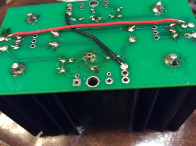
Thanks PB. I was reflowing all terminals on the boards and ended up with a solder blob bridging across 2 leads on a PN2907A transistor. After trying unsuccessfully to remove the blob from this tight spot I ended up pulling the transistor off the board.

After cleaning it up I proceeded to break it trying to reinstall it. The problem is there was still residual solder in each hole that was a complete PIA to remove. I'm afraid the board may be shot because of those efforts. Picture below, notice you don't see those nice shiny metal collars around the 3 holes where the transistor belongs. Will those still conduct?
 

Attachments

  • image.jpg
    image.jpg
    900.3 KB · Views: 116
Yeah, that board is kaput.  You can contact replacementparts(at)bottlehead(dot)com about replacement boards/parts. 

-PB
 
To avoid this in the future pick up a vacuum solder pump, the type with a plunger. They are inexpensive and work well for clearing liquefied solder from pad holes so you can more easily remove and replace components without board damage.
 
Thanks all. The thing that kills me about this is there was nothing wrong with this transistor until I started mucking around looking for the bad connection. I can fix this but I'm still no closer to fixing the voltage issue. With a Kaiju on order I'm feeling the pressure to get this finished. I'm thinking I should just send this in for service. Should I rebuild the board first or send as is?
 
Back
Top