On the front of that board there are pads that say "+ DC -", what voltages do you see at each set?
You are using an out of date browser. It may not display this or other websites correctly.
You should upgrade or use an alternative browser.
You should upgrade or use an alternative browser.
Beepre 2 Coarse Attenuator resistance measurement [resolved]
- Thread starter denteom
- Start date
Neither regulator appears to be working, or there's an issue with your meter that's not letting you resolve the measurement properly.
The 1V could be because there's a short at the socket wiring that's pulling the regulator down, or there could be a soldering issue on the board itself. I would pull out either the wire leaving Reg+ or the wire leaving Reg - (you don't need to do both, just the one that's easy), and see if the voltage coming out of the board pops back up to 6V.
The 1V could be because there's a short at the socket wiring that's pulling the regulator down, or there could be a soldering issue on the board itself. I would pull out either the wire leaving Reg+ or the wire leaving Reg - (you don't need to do both, just the one that's easy), and see if the voltage coming out of the board pops back up to 6V.
Verified that my tester is correct, used my friends multi-tester. So What we did unscrewed the filament board and re-checked and added solder to some joints we think has loose joints. After which we checked again the voltage is now correct, and both tubes now light up.
I thought that was it, when we turned on the music. I still have no sound on the left channel. But the right channel sounds great!
I'll check again later tonight. I'll begin with the speaker cables just in case something also got loose.
I also tried switching the cables to channel two and three still no sound on the left channel.
Where do you suggest I check inside the pre amp?
I found the voltage problem causing no sound on the left channel:
Having the Black terminal at 14
These are the readings on the red terminal:
Terminal 25= 13 VDC
Terminal 30= 13 VDC
Terminal 6 = 120 VDC
Terminal 16= 65 VDC
I've already installed the first upgrade. Are the values for the original build still holds true? The Beepre Manual says Terminal 25 and 30 should be 10. Is 13 volts still okay?
What could be the problem at Terminal 16, is it just loose or just improper soldering at Terminal 16?
Hoping this is the last problem
The first BeePre upgrade will slightly raise that voltage.
I would suggest rechecking that the problematic DC resistances you found originally aren't still there.
I would suggest rechecking that the problematic DC resistances you found originally aren't still there.
The 65V at terminal 16 is troubling. Could you post some build photos?
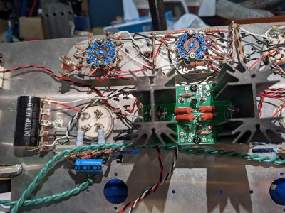
What I would do next is to remove the connections to the large C4S board, rotate it 180 degrees, then reinstall it. If the 65V voltage moves to the other side of the amp, then you have an issue with your C4S board.
Also you should not have to use the isolating parts for the BeeQuiet, and I still believe you have contact between the switch terminals and the metal body of the switch somewhere that's causing issues with that portion of your build.
Also you should not have to use the isolating parts for the BeeQuiet, and I still believe you have contact between the switch terminals and the metal body of the switch somewhere that's causing issues with that portion of your build.
I flipped the C4S and re installed it (mirror image from previous). The 65V still on the same side terminal 16. So the C4S is good. Still not sure what's causing the low voltage in 16.
How about the voltages on Terminal 1 and 11 which reads 170v is that okay? Manual says 150V
How about the voltages on Terminal 1 and 11 which reads 170v is that okay? Manual says 150V
The 170V isn't particularly concerning.
Can you post the voltages on pins 1 and 4 of each 4 pin socket?
Can you post the voltages on pins 1 and 4 of each 4 pin socket?
DC voltage, 300Bs installed, black probe can be on terminal 4.
No, there's nothing wrong with those voltages.
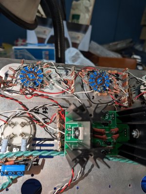
I suspect that the grid on the offending side isn't seeing a good ground reference. Did you see 65V when testing the installation of the C4S board? I would suspect that you have a loose resistor on the terminal strip next to the input selector switch, or possibly a loose wire on that terminal strip.
I suspect that the grid on the offending side isn't seeing a good ground reference. Did you see 65V when testing the installation of the C4S board? I would suspect that you have a loose resistor on the terminal strip next to the input selector switch, or possibly a loose wire on that terminal strip.
During the first installation of the C4S everything was fine. I think it is solder loosening, cause even the filament board that was the problem. My friend help me look for the joints that did not have enough lead. Think problems came out when kept on tapping and shaking the chassis after trimming joints. So you suggest re inspect terminals 16-20 and 26-30, N1-N5. Add more soldering lead to it.
But the voltage problem is at Terminal 16 and probably B2 since a red wire is connected between the two
But the voltage problem is at Terminal 16 and probably B2 since a red wire is connected between the two
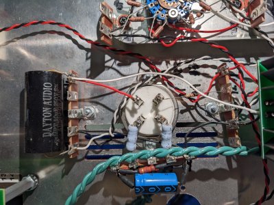
I finally found the problem, yes it was the terminals near the the line selectors, the white wire connected to N1L got disconnected. I think it got snagged by the metal plate holding the attenuators. That wire most likely caused the shorts that I experienced when I was building the resistors at the coarse attenuators. I followed your recommendation and removed the paper washers and returned the #6 washers included in the kit. Did voltage and resistance checks all are in perfect ranges. Connected my DAC to Line 2 then to my headphone amp, sounds great no his or hum, both headphone cups have equal volume, no channel imbalance. Thanks for being patient with me, pointing out my mistakes, also a big thanks to my electrical engineer friend who was willing to help me and trouble shoot the pre-amp during Christmas day.
Still have no sound on my left speaker though, when the DAC was connected to Line 1. I think it is is just the speaker wire connection or again a loose Line 1 solder, but it most likely the former. I can handle it from here. I'll check Line 1 and 3 tomorrow.
Guess this problem is resolved.
I'll work on upgrade 2 mid 2023, meantime relishing upgrade 1.
I'm glad you stuck with it and got it sorted out!
-PB
-PB
Similar threads
- Replies
- 2
- Views
- 3K