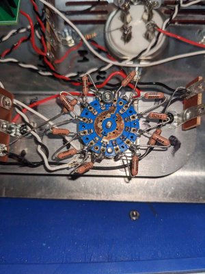
I unscrewed the nut close to Terminal 7, then sprayed contact cleaner. As you can see there is no contact from terminal 7 and the nut. I still get 0 kohm. So just to be clear you recommend removing the attenuator and add paper in between it? Which Standoff? The one connected to the flat stainless steel plate with rounded ends?
You are using an out of date browser. It may not display this or other websites correctly.
You should upgrade or use an alternative browser.
You should upgrade or use an alternative browser.
Beepre 2 Coarse Attenuator resistance measurement [resolved]
- Thread starter denteom
- Start date
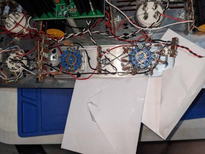
Unscrew the three screws that hold the plate with the level controls to the three standoffs, lift the plate up so it doesn't touch the chassis plate anymore, then recheck that resistance with the attenuator mounting plate no longer touching the chassis.
And the plate that the attenuators mount to isn't touching the BeePre chassis at all?
The idea here is that if there's a short from pin 7 of the switch to the chassis, then lifting the attenuator mounting plate off the BeePre plate will disrupt that connection and you should be able to then measure your 5K reading properly. It's not enough to just remove the screws if the two pieces of metal are still touching.
The idea here is that if there's a short from pin 7 of the switch to the chassis, then lifting the attenuator mounting plate off the BeePre plate will disrupt that connection and you should be able to then measure your 5K reading properly. It's not enough to just remove the screws if the two pieces of metal are still touching.
I would double check that the white and black wires leaving the coarse attenuator are going to the correct spots. They kind of have to be because the stock build wouldn't worth otherwise, but it's worth examining.
Those just come from the left output jacks. Can the attenuator have a factory defect? I know I did the soldering correctly. Would want to resolve this issue before the end holidays. Also I ordered a Crack, if there is a need to return and have something replaced I suggest to have it shipped together with it.
Could you double check that the fine switch doesn't have any influence on this reading? In your photo that you posted, it could actually be the fine switch that is making contact where it shouldn't be, so that's worth double checking.
There's a very good chance that if we sent you a new coarse switch and new resistors that you would be back here with the same problem, so let's take the time to properly sort out what's going on before throwing parts at the issue.
-PB
There's a very good chance that if we sent you a new coarse switch and new resistors that you would be back here with the same problem, so let's take the time to properly sort out what's going on before throwing parts at the issue.
-PB
No, switch the fine control to a different setting and be sure that doesn't influence the reading you're getting.
Hi PB, tried switching the fine attenuator, sometimes it stayed at 5 kohm sometimes it goes to 0 kohm at Terminal 7 of the coarse attenuator. It is not on a fix switch setting. Initially I thought it was the fine attenuator Terminal 2 and 8 but turning it to different positions the results become variable but always 5 or 0 kohm. The resistance at terminal 1 was stable at 5 kohm despite switching different positions.
Finally a ray of hope. Think that narrows down the problem, but I'm not sure what is still causing the problem. Hoping to fix this soon, before Christmas.
Finally a ray of hope. Think that narrows down the problem, but I'm not sure what is still causing the problem. Hoping to fix this soon, before Christmas.
PB:
I pulling up the metal plate where the attenuators are secured. Noticed it had a lesser chance of getting a 0 kohm reading. Must be the metal plate shorting it with something. How do I get rid of that? Do I put back the standoffs and see what happens or do I add some insulators in between?
I pulling up the metal plate where the attenuators are secured. Noticed it had a lesser chance of getting a 0 kohm reading. Must be the metal plate shorting it with something. How do I get rid of that? Do I put back the standoffs and see what happens or do I add some insulators in between?
Thermioniclife
Member
You would have to use nylon spacers instead of metal, but you should actually find the short and correct it.
There would need to be debris or a contact between the metal hardware of the switch and the actual switch terminals themselves. This should be easily visible if you inspect the switches closely.
Finally resolved the problem did 3 things:
1. I changed the number 6 washers to paper washers that I stashed away in my tool kit. I harvested those from my old personal computer motherboard those were used to prevent shorts from the chassis to the computer MOBO.
2. I tightened the hexagonal washers that locks the attenuators to the metal plate. noticed when the shaft touches the metal plate it also caused a short.
3. Sprayed and brushed the contact points. And Voila, shorts gone.
Thank guys. Guess I'll be hearing Christmas carols on my pre-amp after all.
I would recheck your voltages. The twisted green pair of wires leaving the first PC board you installed in the original build is what makes the tube glow, but you could have a loose solder joint going to pins 1 or 4 on that socket as well.
Hi PB:
I tested the filament voltage supply at the Reg+ Reg - that is connected to the B1 and B4. show a voltage around the 2.5. The other side Reg+ and Reg - supplying the A1 and A4 was correct 6.3 volts.
Do I desolder and resolder again the incorrect Reg+ Reg-? shaking it still reveals a firm connection. Hope it just a simple problem
Similar threads
- Replies
- 2
- Views
- 3K