bad reg voltage...

AllanMarcus

New member
Hello,

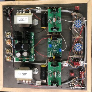
I just finished all the soldering, and passed the resistance tests. I have a problem with the voltage check, and I'm hoping I can get some help narrowing it down.

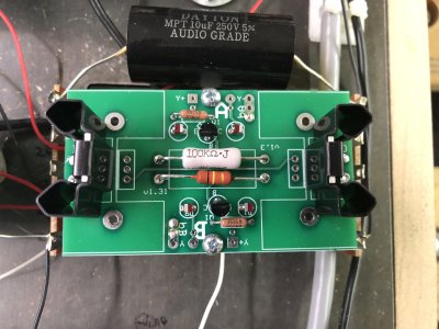
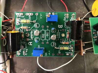
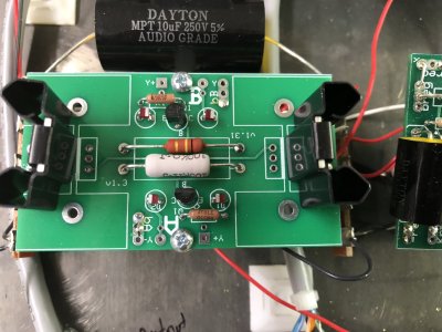
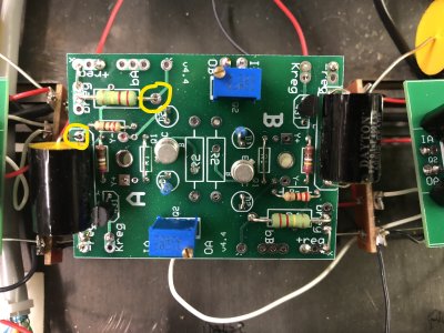
The only out of spec results are breg and kreg on the B side

A side
breg: 221
kreg: 10.66

B side
breg: 283
keg: 1.23

It appears I have a problem on the B side, but I'm not sure what I need to do beyond the obvious reflow and validate the build wth the instructions.

Thanks,

Allan
 
Allan,

Would you post a close up pix of your pc boards and an overall pix of the entire amp underside?
I would be glad to compare to mine...

Alex
 
Thanks.

A little more info. I was able to set the bias to 145 for both sides.
All 4 LED glow
I reflowed all the joints on all three boards.

Still have he same issue.  Are there any other measurements I can take to help isolate this? Should I swap the a and b boards?
 

Attachments

  • IMG_0071.JPG
    IMG_0071.JPG
    1.2 MB · Views: 23
  • IMG_0072.JPG
    IMG_0072.JPG
    3.2 MB · Views: 7
  • IMG_0073.JPG
    IMG_0073.JPG
    3.6 MB · Views: 9
  • IMG_0074.JPG
    IMG_0074.JPG
    3.2 MB · Views: 5
  • IMG_0076.JPG
    IMG_0076.JPG
    2.1 MB · Views: 5
Hard to say. Tonight I will swap the a and b boards and see if the issue follows the board. That will help narrow it down.

I'm also going to print the manual and go though it again, which time checking off items. I would prefer is the manual were a PDF with check boxes, but this is the next best thing. I just hate killing trees.
 
Allan

I looked at your pix and I didnt see any misplaced parts as best as I could tell.
The only comment I would make is some of the solder joints on the center board look like they might not be soldered well on the topside?

Dont know if this is it or not?

But most of the solder joints will have good joints on both sides...

Swapping the boards is something I would do...

Hopefully Paul or Doc will chime in soon as well....

Alex
 

Attachments

  • InkedIMG_0073_LI.jpg
    InkedIMG_0073_LI.jpg
    4.1 MB · Views: 21
adydula said:
Allan

I looked at your pix and I didnt see any misplaced parts as best as I could tell.
The only comment I would make is some of the solder joints on the center board look like they might not be soldered well on the topside?

Dont know if this is it or not?

But most of the solder joints will have good joints on both sides...

Swapping the boards is something I would do...

Hopefully Paul or Doc will chime in soon as well....

Alex

Thanks. The one joint you circled is on the side that is working :-)
 
You could try plugging in a different 12AU7 and see if that changes anything.
 
Low voltage on Kreg and high voltage on Breg do indeed indicate a problem.  What is the DC voltage on the 220K resistor lead closer to the center of the PC board?

Double check that the 431 regulators are where they are supposed to be and not accidentally swapped with a PN2907.

Also be sure that the connections at pins 2 and 7 on the 12AU7 socket are nice and solid on both ends (see page 62).  Just be sure these connections are all tight.

It's also possible that there's an issue with some of the heater wiring on the 12AU7.  Do you see a glowing dot or two on both of the plate structures inside the tube?
 
Thanks CB. I will check all those things first.

The voltage on the 220’s is the same as for
There are four pm2907s on the C4S boards.

Thanks doc.  Tried another tube and same issue.

I swapped the C4S boards, and same exact readings, so I don't think it's on those boards. If CB's ideas don't pan out, I'm gonna walk the manual again  and check everything item.
 
Well, I found my first error. Top of page 58. I soldered the red wire to b4,but did not route it to B5

Hopefully that’s it, but I will continue to check the rest of the manual. 

Ug.

Update: that was it! Bias all done, and waiting for the transformer to cool to flip it over and try the final instruction from the manual - throw on some music!

I don’t understand why you guys didn’t notice this in the pictures :-)
 
Doc B. said:
http://www.instructables.com/id/Homemade-Xray-Machine/

Which socket on the mainline do the x-ray tubes go into?

OK, seriously. I have a question. The heat shrink the got fitted over a few wires. Do they just shrink over time by themselves?
 
Wow!!

I was wondering why Doc posted that X-ray machine link!!! LOL

I just looked at page 58!! Ha!

Thats a good one...

So how does it sound / work??

I got out 4 amps yesterday and listened to each for 30 minutes...and all are good, BUT

when I got back to the mainline it was subjective heaven.

Alex
 
adydula said:
Wow!!

I was wondering why Doc posted that X-ray machine link!!! LOL

I just looked at page 58!! Ha!

Thats a good one...

So how does it sound / work??

I got out 4 amps yesterday and listened to each for 30 minutes...and all are good, BUT

when I got back to the mainline it was subjective heaven.

Alex

I really only got a few minutes with it because it was late and I had stuff to do before I went to bed. I'll get a little time tonight, then I'm out of town until sunday. Sigh.

From what I've heard, very good. I made a box that lets me plug into up to amps, and outputs to one headphone. This lets me switch between amps.

https://sites.google.com/marcusfamily.info/diynotes/my-stuff/balanced-switchbox?authuser=0

So far I can hear some difference between the Mainline and the Black Widow 2, but I haven't identified what that is yet. I think the mainline is a little smoother. Plus, from what I understand, the Mainline (and all tube amps) need some burn-in time.

Thanks for all your help.
 
My point about the x-ray machine was that it would be pretty difficult for us to spot a miswire on a tube socket with PC boards blocking the view of the sockets in the photos.
 
Back
Top