B6 voltage too high on Paraglow II PSU update

KGW

New member
Hi Paul,
Doc B. suggested that I ask you if I still had issues...
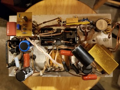
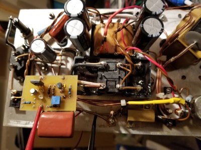
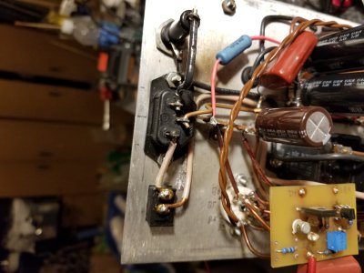
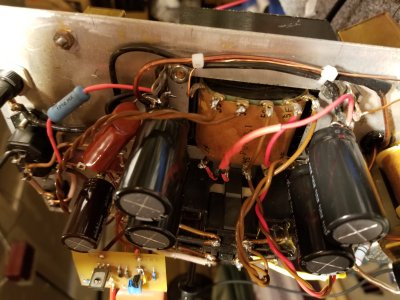
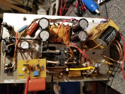
I replaced the power supply caps, etc per the earlier instructions on one of my amps. The original voltages were quite high. I hooked my octopus/oscilloscope up and found that one of the LT1431IZ shunt regulators was not working. So I ordered so new ones. I put in the replacement, but I can't get voltage on B6 to adjust to 215VDC.

Here are the measurements on my 2 amps:

#1 (unmodified):
B+1 (first cap) 447 VDC
B+2 (second cap) 432 VDC
after 15k0 5W resistor - 198 VCD
B6 - 215 VDC

# 2 (with PSU upgrade)
B+1 (first pair of caps) 451 VDC
B+2 (second pair of caps) 437 VDC
after 15k0 5W resistor - 234 VCD
B6 - 267 VDC

Any ideas? Can I provide any more info that would help?

Kevin
 
Yeah, pictures would be good.

You said you replaced the caps, etc - does "etc" mean the hefty cathode resistor which must have replaced the series 1.8K and 1.5K resistors that came with the Paraglow II upgrade package? No other changes from stock?

Just trying to be sure we understand the starting point. PB has done the necessary mod more than once, but I'm interested in this thread too, especially for historical reasons.
 
I'm having trouble up;loading the pix, so I'll try breaking them up
This are the unmodified and modified amps
 

Attachments

  • 20200517_111140.jpg
    20200517_111140.jpg
    3.4 MB · Views: 22
  • 20200517_111120.jpg
    20200517_111120.jpg
    3.3 MB · Views: 9
more pix of the modified amp
 

Attachments

  • 20200517_111116.jpg
    20200517_111116.jpg
    3.1 MB · Views: 6
  • 20200517_111111.jpg
    20200517_111111.jpg
    3.8 MB · Views: 6
and more
 

Attachments

  • 20200517_111101.jpg
    20200517_111101.jpg
    3.5 MB · Views: 9
  • 20200516_200754.jpg
    20200516_200754.jpg
    3.9 MB · Views: 3
Here the original thread:

"The minimum process for rebuilding Paraglows involves mounting a pair of 6 lug terminal strips on each power transformer,
then moving the power supply to that location.  We usually used at least a pair of 220uF/250V caps in series to get 500V
rated caps.  The next area to address was to dramatically increase the wattage rating of the cathode bias resistor.
For the recent rebuilds I have done, I have used 25-50W parts instead of the 10-12W parts provided with the kit.
These run cooler and last much longer.
Along with the new cathode bias resistor, a new cathode bypass cap is also called for.

The series caps should also have 1 megohm resistors in parallel with each cap to equalize the charge across the caps.
This update is fairly tricky to implement because of the additional parts being sandwiched into the rather primitive
layout (I can say that since I did it) and it might be something that is best sent to PB to install."

-----
A few questions and photos of my amp attached (Note: mine has the Buddha CMC filter and RRSF and some parts upgrades - otherwise a regular PGII).

I just wanted to confirm what parts I need (doing both amps)

4: 6 lug terminal strips (https://www.mouser.com/ProductDetail/Keystone-Electronics/822?qs=sGAEpiMZZMvlX3nhDDO4AO8cnfwRjH5XUfPLeM1KNm8%3D)
8: 220uF/250V caps (https://www.mouser.com/ProductDetail/Nichicon/UVR2E221MRD?qs=sGAEpiMZZMtZ1n0r9vR22VJXtNfMoEIxa1JdRAAGvYw%3D)
8: 1M resistors (carbon film?, power rating?)
2: new cathode bias resistor - Currently using Arcol 3k3/25W - is that ok? - note this was the value measured from JT's original parts
2: new cathode bypass cap 220uF (https://www.mouser.com/ProductDetail/Nichicon/UCY2D221MHD?qs=sGAEpiMZZMtZ1n0r9vR22awqI6nzE%2FsTCBQlAGkaPmE%3D)

NOTE: the new amp does no have the RRSF
 
OK, things are making more sense now.  The balancing resistors can be a 1M/0.25W, that's sufficient.

Your new power supply is working properly.  The Tucker shunt reg board is possibly not working, or you have half a driver tube not lighting up or half a driver tube that's not conducting anymore.

So, verify that both halves of the 9 pin tube are glowing, then swap 9 pin tubes between amps.  If that doesn't fix the issue, then it's down to the Tucker board.  When I run into those, I just put the Paramount soft-start driver into the amp and call it good. 

As far as the Arcol 25W resistor goes, can you send a link to the part you bought?
 
I'll add that, based on my recent work on pboser's Afterglow, the 3300 ohms is correct, but its bypass should have a higher volt rating - it has 250v 200v across it. (added: But the startup transient goes much higher.) There are 315v and 350v rated parts - in fact that's probably what was used for the HV cap replacement.
 
Here is the part: https://www.mouser.com/ProductDetail/ARCOL-Ohmite/HS25-3K3-J?qs=sGAEpiMZZMtlubZbdhIBIEidPY%252Bx%2FLaaoOHGETo8UTQ%3D

I used the same set of tubes to test the 2 amps, so I don't think that is the issue.

I can hook up the octopus and scope up again and test the other parts on the Tucker boards.
I replaced the trim pot and the shunt reg on the 1 board (on the problem amp). Note, when I first built it, I had a similar issue and JT fixed it for me (before I had the scope/octopus). JT used a Huntron Tracker.
 
Filaments are all good.
Comparing the parts one the 2 boards with the octopus/scope looks the same.
LEDs all come on. The 2 resistors in parallel near the trim pot look a little dark. I can't read the values.
When I try to adjust the trim pot, the voltage only changes a volt or so.

Do you recall the resistor values?
 

Attachments

  • resistors.png
    resistors.png
    435.1 KB · Views: 10
Uh-oh! I think I made a mistake. With the PGP8.1 you get 200v across the cathode resistor and 60mA through the 2A3. I'll fix my post.
 
What is the startup voltage? Note: I have a center tap ground lift switch installed. If I need a 50W part, I can get them. But I should maybe get some new ones to try. I seem to recall that they are 6N1P.
 
kgwrocks said:
My 3k3 resistor is 25W

250/3300=0.076 amps
250*0.076=18.9W

So that part should be fine
No, not by a long shot. The 25W rating on the Arcol HS-25 series resistor assumes you have it mounted to a piece of aluminum that is 83 square inches and 1/16" thick.  If you had the whole top plate with no holes in it and no other sources of heat, that would only be 60 square inches.  In reality the top plate isn't worth much as a heatsink for a resistor like this, as there are holes in it and other source of heat.  These are rated for 9W with no heatsink, and the max temperature rating for the resistor is 200C, so it's entirely possible that 9W of dissipation gives you 200C.  We work really hard not to run any resistors or transistors in our amps over 100C. 

For 19W of dissipation, I would want a resistor or combination of resistors rated for 60W and not a type that requires a heatsink.

This is what I use in my Paraglow rebuilds:
https://www.mouser.com/ProductDetail/Ohmite/L50J3K0E?qs=sGAEpiMZZMtlubZbdhIBIMQod%252BtVNHwBcdGFIgmte38%3D
To trim it out to 3.3K, a ~300 ohm 5W resistor can be added in series.  These are cumbersome to mount, but they are large enough not to experience a whole lot of temperature rise.
 
Wow! Shows what I know. Thank you for explaining clearly.
Do you have a part number for the 300r0/5W resistor? Is there anything else I should replace (as long as I am ordering parts)?

Could this have something to do with my original issue?
My guess is that the resistor got too hot and took the shunt reg with it. I will check if the Arcol resistors died.
 
Do you have info/parts for the soft start circuit? Sounds more convenient than my ground lift switches.
 
You can get a good chunk of the parts you'd need from our Smash-up upgrade.  Beyond what's in that kit, you'd need a few extra small parts to replace a few of the resistors in the kit, as well as a few extra parts if you want to implement the adjustable biasing feature that we added. 
 
JTs early shunt reg boards had a potential issue in that they would blow if the trimpot was turned all the way to the low end. Pretty sure that he would preset them close to where they needed to be when he packed those kits in order to avoid the issue.
 
Back
Top