If anybody had a wager going, it's time to collect. I've failed the Final Voltage test, and, of course, am flummoxed.
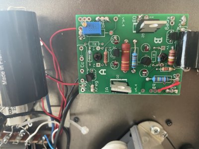
So, here we are: I've added the board and all that, put in the lamps, and fired the amp. And get 3volts on the A side and 2 volts on the B side. I've been delving a little bit more, and so I get 400V at the non grounded part of the resistance in R2 on the A side, as well as at the LEDs, and at one of the pins of the MJE5731A on the A side, the one closest to the potentiometer. I get 389V at the other external pin of the MJE5731A, but only 3V at the central one, as well as at OA and onwards. So there is something wrong with my circuit somewhere, probably in the part that is beyond the MJE5731A on the A side, but I can't figure out where, and so, here I am again, asking for help.
So, here we are: I've added the board and all that, put in the lamps, and fired the amp. And get 3volts on the A side and 2 volts on the B side. I've been delving a little bit more, and so I get 400V at the non grounded part of the resistance in R2 on the A side, as well as at the LEDs, and at one of the pins of the MJE5731A on the A side, the one closest to the potentiometer. I get 389V at the other external pin of the MJE5731A, but only 3V at the central one, as well as at OA and onwards. So there is something wrong with my circuit somewhere, probably in the part that is beyond the MJE5731A on the A side, but I can't figure out where, and so, here I am again, asking for help.