You are using an out of date browser. It may not display this or other websites correctly.
You should upgrade or use an alternative browser.
You should upgrade or use an alternative browser.
Am I assembling it right? [resolved]
- Thread starter hoy83
- Start date
You need to wrap the wires up and over the socket pin connections, then solder them. If you just take a wire and pass it through a hole, then solder that, you won't get a great connection. A9 is a perfect example where the wire pokes through and off to the side. This wire needs to be bent up and over the tube socket terminal, crimped, then soldered.
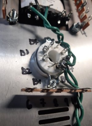
The wires going from the power transformer to B7 and B8 need to be pressed down against the chassis plate.
The solder joint at B8 is not adequately heated to be properly soldered.
It's also worth mentioning that the 6080 tube has a keyway on the base and if you don't plug it in properly, it won't light up. It may also break when you go to remove it from the socket.
Yes, the 6080 is the bigger tube. It should have 6080 written on it.
Pull it out of the socket and look at the bottom. There's a black plastic post in the middle of the base with a piece that projects out, that needs to be plugged in so it fits properly into the 8 pin socket.
Pull it out of the socket and look at the bottom. There's a black plastic post in the middle of the base with a piece that projects out, that needs to be plugged in so it fits properly into the 8 pin socket.
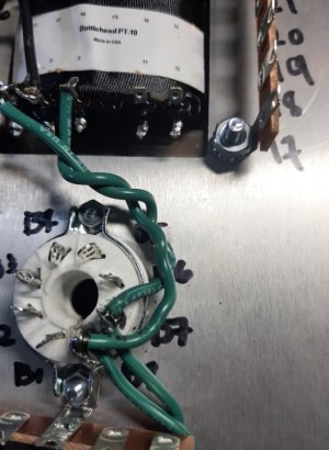
That's looking better. The ends of the green wires going through the sockets can be wrapped around and crimped so they stay tight.
Yes, bend the wire into a hook, insert and crimp it round the connector. It should be fixed mechanically before soldering. It's more than just a belt and braces approach, you get more surface area for the solder to flow around. The solder should look smooth and shiny before you quickly remove the solder tip. Don't give it a poke to try and fix if if it looks a bit dodgy, flow it out again.
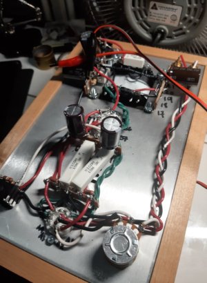
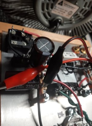
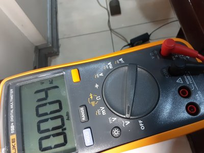
so... I THINK, I finished assembly of the crack.. problem is I don't know how to test resistance.. the instruction says to attach the black lead to the ground buss, I don't know which one is the ground buss on terminal 12u.. I attached pictures of where I clipped my black lead for the multi meter. and where should I set the multi-meter dial to? to 12 o clock on the ohm sign?
.
anyway if I got it right and clipped the black lead on the correct place, I'm getting more than 0 ohms on some that needs to be 0 ohms..
here is the breakdown:
Terminal:
1. * (I don't know what this asterisk means so I didn't measure those with asterisks)...
2. *
3. 0.1 to 0.2 ohms
4. *
5. *
6. 0.1 ohms
7. 2.952 k ohms
8. 0.1 ohms
9. 2.944 k ohms
10. around 39. something with an M beside an ohm sign in the dmm
12. 0 ohm
13. *
14. 0.1 to 0.2 ohms
20. 0.0 ohms
22. 0.0 ohms
B3. 2.952 k ohms
B6. 2.954 k ohms
RCA jack center pin black. 103.1 ohms
RCA jack center pin red. 99.1 ohms
RCA jack ground tab black 1.1 ohms
RCA jack ground tab red 0.3 ohms
I think I got it wrong..
thanks in advance for any help..
Attachments
Thermioniclife
Member
Touch the clips together, what does your meter read?
12U is a ground connection. I'm not quite sure what you're asking, that's where your black meter probe should connect.hoy83 said:I don't know which one is the ground buss on terminal 12u..
The asterisk is explained on page 47 where the resistance values are posted.hoy83 said:1. * (I don't know what this asterisk means so I didn't measure those with asterisks)...
The values at 7 and 9 should be 2.9K, not just 2.9 (same for the center pin of each RCA jack). 43m would be OK on 10 (that would be 0.04 ohms) but 43M would definitely not be OK.hoy83 said:6. 1.0 ohms
7. 2.952 ohms
8. 1.1 ohms
9. 2.944 ohms
10. around 43. something with an M beside an ohm sign in the dmm
The value at 10 would have me wanting to see the headphone jack wiring and the octal socket wiring in a bit more detail.
Thermioniclife said:Touch the clips together, what does your meter read?
0.0 ohms when I switch my multi-meter to the ohm sign
Thermioniclife
Member
0.0 ohms is very good, most meters read around .02-.03 ohms with the probes touching and you can consider that 0 ohms.
Paul Birkeland said:12U is a ground connection. I'm not quite sure what you're asking, that's where your black meter probe should connect.
The asterisk is explained on page 47 where the resistance values are posted.The values at 7 and 9 should be 2.9K, not just 2.9 (same for the center pin of each RCA jack). 43m would be OK on 10 (that would be 0.04 ohms) but 43M would definitely not be OK.
The value at 10 would have me wanting to see the headphone jack wiring and the octal socket wiring in a bit more detail.
yes I corrected the values on my previous post, it's k. not sure with ten, do you mean a small letter m or big letter M? I switched to manually holding the probes with my hand with the black lead on the 12u terminal and using the red lead to measure, it measure below 1ohm as opposed to using an alligator clip which I think is a bit inaccurate in giving me readings a while ago. I updated the values on my previous post.. so is it correct that I just attach my black lead to 12u that would be the correct way? I'm really suspicious about the terminal 10.
hoy83 said:with terminal 10 my dmm goes crazy, going from 40kohms to 80+kohms..
Paul Birkeland said:The value at 10 would have me wanting to see the headphone jack wiring and the octal socket wiring in a bit more detail.
Thanks, that seemed to work, there was a loose connection on the headphone jack, soldered it and terminal 10 was 0 ohms..
Ran into a problem again though.. the voltage test was a little over the limit specified in the manual.
Here are the terminals:
terminal 2 188v - 189v
terminal 4 189v
terminal 7 116.8v
In the manual it says terminal 2 and 4 should be around 170v, and terminal 7 is at the maximum 115v. Is this ok?
thanks in advance.
I wouldn't be too concerned by those.
Similar threads
- Replies
- 6
- Views
- 4K
- Replies
- 16
- Views
- 26K