ALL212
Member
Here we go...
As way of introduction my first Bottlehead was a Crack done about a decade ago as a Christmas gift from my wife. And I might be off by a couple of years...
Since then I've run through 3 more Crack builds, a Stereomore, SEX, both of those battery powered kits, Crack-a-2a, Mainline, Reduction and Eros... and I might be missing one or two...
I have sold off a few but have 2 Crack's here (the BAC and the C4), the Crack-a-2a, the Mainline, SEX and Stereomore (converted to 45's) and the Eros. Since the Moreplay came out I've been waiting for the upgrade kit and a sale... and time. Recent Grandchildren have complicated the time issue but I'll figure that out.
I've not ever ended up with a stock build. This one won't be different but I'll be pulling most of the upgrades out of "stock".
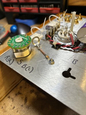
One stock item was a passive pre I built with a Goldpoint selector and Cardas CTFA RCA inputs to be repurposed for the Moreplay.
I found a "trick" while attempting install of the sockets and the pair of strips. I found that a simple Q-tip can be used to hold the first nut in place to tighten it by just jamming it towards the strip side and if you pull most of the cotton off of the other end you can use it to install the 2nd nut by sticking that end of the Q-tip into the nut to hold it and get it into place. As you tighten the screw it will back the Q-tip out.
I also have in my arsenal a nut installer. Not much more than a plastic tube that can hold the nut while putting it in place. Not sure where to get those but it sure makes life easier.

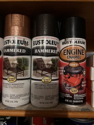
Getting paint on the plate is a bit of a challenge this time of year. I live in Rockford, IL - north central IL, just shy of the chedder curtain. It's a bit nippy... I use one of those oil filled heaters to warm the plate up (and the other parts I've painted) and then once painted to put some heat back in it to cure/dry it. I tend to rush this part... no patience. But it went well. Black and Copper crackle paint. I like the finish and this isn't the first kit to get this color scheme.

Stopping here for today. Might be a day or two before more progress is made. I think it's the Mainline base I'm using as a build box until I get a base built. I don't want to use the provided base but will use it as a template.


As way of introduction my first Bottlehead was a Crack done about a decade ago as a Christmas gift from my wife. And I might be off by a couple of years...
Since then I've run through 3 more Crack builds, a Stereomore, SEX, both of those battery powered kits, Crack-a-2a, Mainline, Reduction and Eros... and I might be missing one or two...
I have sold off a few but have 2 Crack's here (the BAC and the C4), the Crack-a-2a, the Mainline, SEX and Stereomore (converted to 45's) and the Eros. Since the Moreplay came out I've been waiting for the upgrade kit and a sale... and time. Recent Grandchildren have complicated the time issue but I'll figure that out.
I've not ever ended up with a stock build. This one won't be different but I'll be pulling most of the upgrades out of "stock".
One stock item was a passive pre I built with a Goldpoint selector and Cardas CTFA RCA inputs to be repurposed for the Moreplay.
I found a "trick" while attempting install of the sockets and the pair of strips. I found that a simple Q-tip can be used to hold the first nut in place to tighten it by just jamming it towards the strip side and if you pull most of the cotton off of the other end you can use it to install the 2nd nut by sticking that end of the Q-tip into the nut to hold it and get it into place. As you tighten the screw it will back the Q-tip out.
I also have in my arsenal a nut installer. Not much more than a plastic tube that can hold the nut while putting it in place. Not sure where to get those but it sure makes life easier.
Getting paint on the plate is a bit of a challenge this time of year. I live in Rockford, IL - north central IL, just shy of the chedder curtain. It's a bit nippy... I use one of those oil filled heaters to warm the plate up (and the other parts I've painted) and then once painted to put some heat back in it to cure/dry it. I tend to rush this part... no patience. But it went well. Black and Copper crackle paint. I like the finish and this isn't the first kit to get this color scheme.
Stopping here for today. Might be a day or two before more progress is made. I think it's the Mainline base I'm using as a build box until I get a base built. I don't want to use the provided base but will use it as a template.


")


