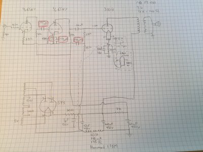
I thought I'd ask this question here because some people used to know George Wright, and some of his ideas contributed to early BH products. I've made a breadboard to try different amplifier circuits, starting with old standards like the Fi Primer and JE Labs 300Bs. I love Wright equipment, and have successfully breadboarded an amp that is the front end of his WPA 3.5 (2A3) but with a 300B output stage.
I'm curious to try the Mono 8, and while I haven't found a schematic anywhere (I know, he never wrote them down), I did attempt to reverse-engineer it from hi-res pics in a recent internet sale.
There are 3 components in the 6SN7 stage that I can't quite figure out the values of. Does anyone recognize them or happen to know what their values are likely to be?
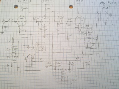
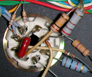
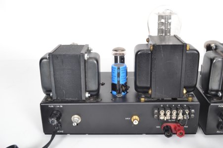
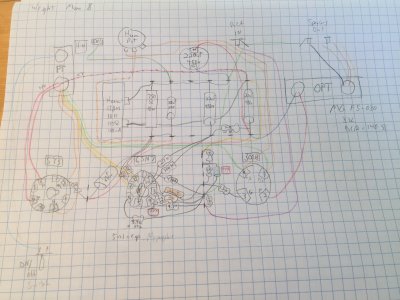
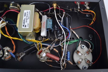
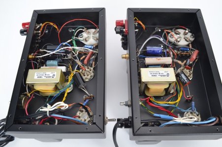
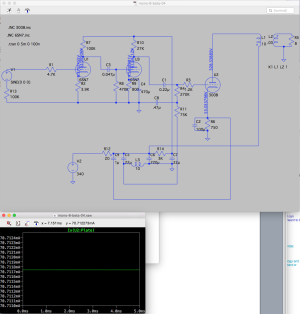
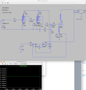
I've attached pics from a recent internet sale, a drawing which duplicates and simplifies the layout, and my attempt at rendering a schematic.
What I don't know are the following three things in the 6SN7 stage (squared-in with red pencil in the drawings):
* Small red coupling cap from plate 1 to grid 2 (pins 5 —> 1)
* Second cathode (pin 3) resistor and little white bypass cap (peeking out from under the big red coupling cap)
(common values here are usually 23K-30K and 47uF 160V, but who knows?)
* Silvery-blue “F1" cap (I might see numbers 047 -- possibly 0.47uF?)
(it connects between the 270K and 75K resistors that go to the ground leg of the first [rightmost] 22uF/450V PS cap)
Many thanks for any insight you might provide, and sorry for posting so much info.
I'm curious to try the Mono 8, and while I haven't found a schematic anywhere (I know, he never wrote them down), I did attempt to reverse-engineer it from hi-res pics in a recent internet sale.
There are 3 components in the 6SN7 stage that I can't quite figure out the values of. Does anyone recognize them or happen to know what their values are likely to be?
I've attached pics from a recent internet sale, a drawing which duplicates and simplifies the layout, and my attempt at rendering a schematic.
What I don't know are the following three things in the 6SN7 stage (squared-in with red pencil in the drawings):
* Small red coupling cap from plate 1 to grid 2 (pins 5 —> 1)
* Second cathode (pin 3) resistor and little white bypass cap (peeking out from under the big red coupling cap)
(common values here are usually 23K-30K and 47uF 160V, but who knows?)
* Silvery-blue “F1" cap (I might see numbers 047 -- possibly 0.47uF?)
(it connects between the 270K and 75K resistors that go to the ground leg of the first [rightmost] 22uF/450V PS cap)
Many thanks for any insight you might provide, and sorry for posting so much info.
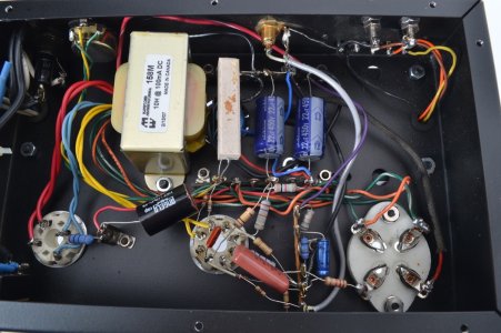

") Also, your suggestion of 2K for the second 6SN7 cathode resistor is close. I read your comment on my phone, and then looked at one of the pics I'd attached and could clearly see the stripes are brown-black-red, or 1K. Unless it's grey-back-red, which would be 8K, but probably not. Funny, the colors didn't show up as clearly on my large computer monitor.
Also, your suggestion of 2K for the second 6SN7 cathode resistor is close. I read your comment on my phone, and then looked at one of the pics I'd attached and could clearly see the stripes are brown-black-red, or 1K. Unless it's grey-back-red, which would be 8K, but probably not. Funny, the colors didn't show up as clearly on my large computer monitor.