Wondering if installing my heat sink may have damaged a Schottky rectifier?

d_composer

New member
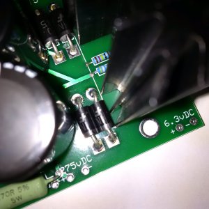
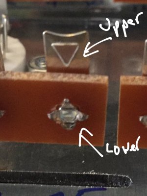
Hi -- the bottom part of my heat sink was very difficult to install today because my rectifiers were leaning to the right just a little too far. When I finally got my heat sink in, I noticed that it pushed my rectifiers over a little (see pic). My DMM doesn't show any voltage difference between these rectifiers and the other pair on top, but could there possibly be any other harm done that I should be aware of? Or any other tests I can do with my DMM? This is my first bottlehead build and I don't want to mess it up! Thanks so much in advance!
 

Attachments

  • IMG_20170219_213541.jpg
    IMG_20170219_213541.jpg
    1,009.4 KB · Views: 72
Does your DMM have a diode test?

"On a (digital) DMM, there will usually be a diode test mode. Using this, a silicon diode should read between .5 to .8 V in the forward direction and open in reverse. For a germanium diode, it will be lower, perhaps .2 to .4 V or so in the forward direction. Using the normal resistance ranges - any of them - will usually show open for any semiconductor junction since the meter does not apply enough voltage to reach the value of the forward drop. Note, however, that a defective diode may indeed indicate a resistance lower than infinity especially on the highest ohms range. So, any reading of this sort would be an indication of a bad device but the opposite is not guaranteed." That's from http://www.repairfaq.org/sam/semitest.htm#sttdj

Am I right in thinking that the diodes just got shoved/bent a bit when you put the heat sink on? It's been a few months since I built my kit, but unless you really gouged out part of the body, I'd imagine it's more that the leads bent.

Mary
 
Thanks Mary. Yeah, there's no gouging and all the rectifiers are reading the same thing when I use the diode test on my DMM (~131 forward V). All the diodes give off the same resistance too when I test them so I'm guessing I'm safe?
 
I'm not an electronics expert by any means, but I recall those Schottky diodes seemed pretty beefy, especially the leads.

I wonder if the experts have Monday off...
 
I think you'll be just fine.  There's a section in the manual that has you test the output of that PC board, and if there's an issue, it will pop up immediately there when you go looking for 6.3V on the 6.3V pads. 
 
Caucasian Blackplate said:
I think you'll be just fine.  There's a section in the manual that has you test the output of that PC board, and if there's an issue, it will pop up immediately there when you go looking for 6.3V on the 6.3V pads.

Awesome, that sounds perfect!

Thank you all!
 
Ok! Just got to the part in the build doc where I test the power distribution board and it passed with flying colors! Yay! Thanks again!

Another question: the upper and lower terminals seem backwards in the instruction's pictures. Upper is the tab hanging off the terminal strip while lower is the hole going through it, right? Or doesn't it matter as long as I stick to a convention?
 
Back
Top