what if I wanted to add a third input to my Quickie...

denti alligator

New member
...would the simplest way be to add another set of RCA plugs and a second toggle switch.

how would I wire this? and what would the easiest way be to install these into the chassis? drill sizes?
 
I would get a 3 way or even 4 way switch and do it that way. If you got a 4 way you could later add 4 inputs, or even do it from the get go. Adding a second switch would be too many switches in audio path IMO.
 
Simplest is to get an input switch with all the RCA jacks installed at Radio Shack.  Dan has often suggested this.  Otherwise you might use a DPDT toggle switch to change between inputs 2 & 3.  That would feed the stock switch.

Eric's suggestion above is a better way to do it.  It looks better too.
 
On the older Quickie, you could replace the toggle with a 2P3T toggle, though they can be a little unusual to wire.

On the new Quickie, you would most likely have to go to a double deck rotary switch, or find a single deck that is 4P4T.
 
On the new quickie, couldn't you remove the d-cell battery control from the rotary, use the rotary in a typical 3 way fashion, and control the d-cells with a dpdt? This gives a traditional on/off switch and 3 way rotary input selector right?
 
I'm also wanting to add another input. OP how did you end up sorting this out? Pictures and guidance appreciated!
 
Alright guys, take mercy on me. Just got the quickie in the mail tonight (so excited!), and I'm looking at the schematics trying to figure out how to add in a DPDT on/off toggle and rewire the 4p3t as a source selector for 3 sources. This is my first big project and I don't want to screw it up, so I have a couple of questions.
  • Can I just splice the DPDT on/off into the black leads from the D cells before they go to the terminal strips? I just happened to be by a RadioShack the other day and picked this up (http://goo.gl/rOaSWR) will it fit the bill?
  • I'm having a hell of a time figuring out how to wire the switch for use as a three source selector. I'm thinking that the signal wire from the third RCA will go to terminals 1&4 and that terminals  7/8/9 and 10/11/12 will be daisy chained together? Am I on the right track? If not could someone draw me a map or at least point me in the right direction?
Thanks in advance, your help is always appreciated.

Witold
 
WK3K said:
This is my first big project and I don't want to screw it up, so I have a couple of questions.

Hmm, there is something really important to consider here.  If you run into trouble with your Quickie after you've redesigned it, we will have a very hard time helping you. 

It wouldn't be impossible to just build it stock, get it working correctly, then perform these modifications.  You'll just need a little extra wire.  (Which you probably need anyway)
 
Prudence is the better part of valor. Stock build it is, mods later. Just out of curiosity, and because this whole thing is a learning experience, did I at least have the switch configuration correct?

Thanks!

W.
 
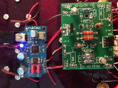
Alright y'all, after building the stock quickie and adding the PJCCS (very happy with it!), I've gone ahead and tried to add a third input to the quickie. I built a little GrubDAC and wired it in for the third input, but I'm not getting any sound from that input (other two are working great). The DAC LED lights up and my computer recognizes it, but I get zero sound when I switch to that channel.

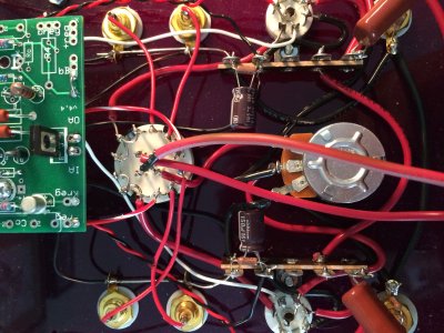
I'm not sure if the problem is in the DAC or in how I wired it in. I connected the output grounds to the grounds on the RCA plugs, then added little jumpers between rotary terminals 7&8 and 10&11. I ran the right and left channels to terminals 1 and 4 on the rotary, respectively. I added a simple DPDT switch between the D-cells and rotary to give the amp an on/off. I've attached some pictures here, maybe someone can set me straight if I've bungled things.

I ran resistance checks and I'm getting 1.5K at rotary terminals 7-12, instead of ~1.07k, I still get infinite at rotary terminals 1-6. Batteries were in, but amp was switched off.

I figured I'd start here and work my way back to the DAC, since I kinda winged this part... :)

Thoughts?

Thanks in advance!

Witold


Attachments

  • photo 1.JPG
    photo 1.JPG
    767.9 KB · Views: 157
  • photo 2.JPG
    photo 2.JPG
    2.1 MB · Views: 168
I get the same voltage readings regardless of which channel (1-3) I set the rotary to. They all seem to be within normal limits for the PJCCS quickie.

W
 
Thanks Paul! I was going to update this last night, but it looks like the site was down. I have been poking around at the DAC and have gotten it to play (sporadically). Anyhow, I'm satisfied that the problem is with the DAC and not with the quickie and that this approach for adding an extra channel is sound. I appreciate the help!

Witold
 
Caucasian Blackplate said:
http://www.mouser.com/ProductDetail/NKK-Switches/M2044SS1W01-BE-RO/?qs=sGAEpiMZZMvudeGI7i40XP93sFwtDpTaZ1OHH5C0U5Y%3d

This one would probably work.  It can be somewhat difficult at times to tell if a toggle switch has a momentary position on it or not.

You'll have to analyze the datasheet and pay careful attention to the "external connection" reference therein.

-PB

OK, I'm finally gonna try this. The part linked to here is no longer available. Can someone point me to a switch that would fit where the existing switch is already mounted in the Quickie. My plan is to add RCA jacks between the input and output jacks.

Also, the switch linked to here is a DP3T switch. Is that what I need? or is it a 2P3T switch?
 
Back
Top