cnledesma17
New member
Hello,
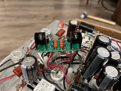
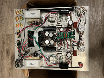
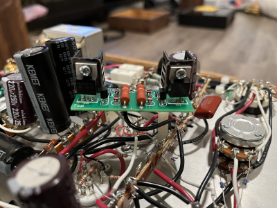
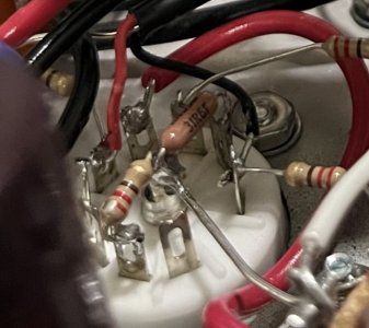
I recently completed my Stereomour II Kit, and while performing the final voltage check, I noticed that the T7 and T14 DCV were both reading ~110 VDC and ~100 VDC, which failed to meet the recommended range. All LEDs illuminate on the circuit board. I tried swapping the tubes around and reheated any suspected cold joints with no improvement. I am at a point where I am not sure what to do. All resistances and other voltages are within the range.
Thank you,


