Troubleshooting completed kit

Wrekless

New member
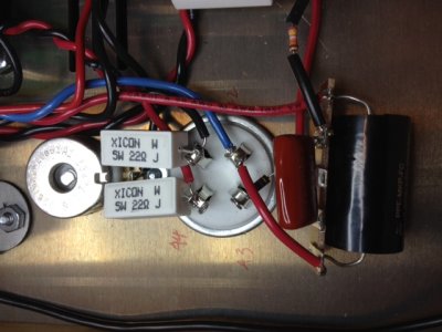
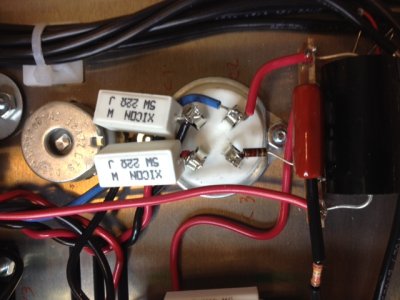
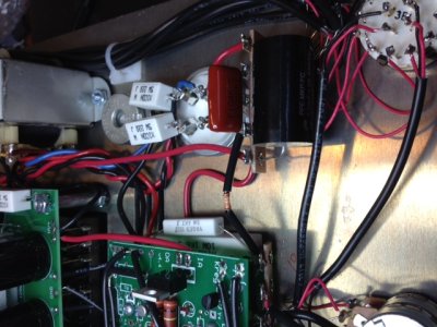
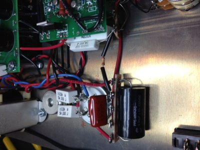
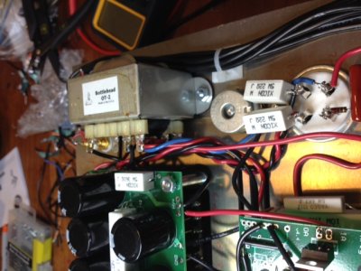
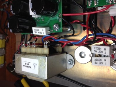
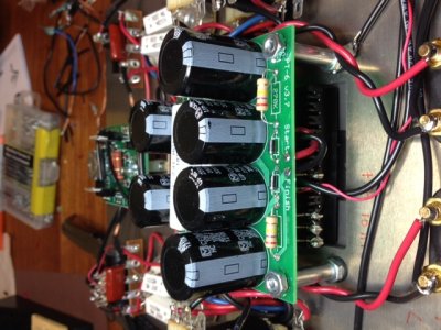
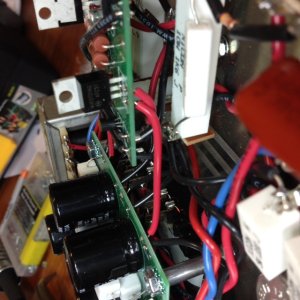
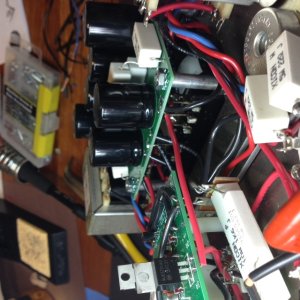
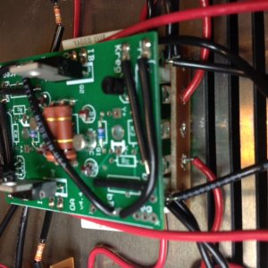
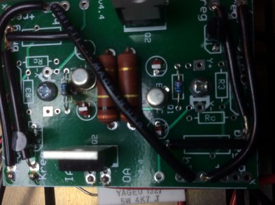
These are the resistance readings for my just completed 2A3  that may be off the mark.  Measured with a Wavetek 27XT.

T1  bounced around, then 0
T2  bounced around, then 0
T14  0
T15  0
T17  0
T19  0
A2  0
C2  0

These are all asterisked in the manual, meaning the values may vary from ohmmeter to ohmmeter, but watch out for a reading of zero in one of the terminals.  Since I got zero for all of them, and the other readings were spot on, I went ahead and powered up the amp.  12AT7 glowed, couldn't tell if 2A3's were lit before I saw a wisp of smoke, went ahead and shut amp down.  Follow up readings are all the same as above.  Not sure where smoke originated from.
Any suggestions?  Yes, I'm not firing amp up again until ALL readings are correct.  Thanks in advance, Eric.
 
Wrekless said:
These are all asterisked in the manual, meaning the values may vary from ohmmeter to ohmmeter, but watch out for a reading of zero in one of the terminals.  Since I got zero for all of them, and the other readings were spot on, I went ahead and powered up the amp. 

As is stated in the manual, resistances of "0" at those terminals mean that there is a miswire.  If there was some way we could make this clearer in the manual, please let us know, as the potential for damaging your amplifier by turning it on in this state is high.


A2/C2 being zero means that the power supply is short circuited to ground.  I think photographs of the build will be most helpful.  Off the top of my head, I think you might have the 4 pin sockets mounted backwards, but it's just hard to be sure.

-PB

(Sorry for the mild rant)
 
Thanks for the quick reply, and duly noted on the rant.  Attached are the photos of the 4 pin sockets.  Eric
 

Attachments

  • photo.JPG
    photo.JPG
    112.9 KB · Views: 156
  • photo 2.JPG
    photo 2.JPG
    111.6 KB · Views: 164
I'm pretty sure that Paul wanted to see the power supply.  Most especially a good picture of the diodes/transformer feeds and the capacitors/resistors for each channel. 

Pictures like you posted are good, and in focus so just take some more shots and that will help.
 
Here's some more...
 

Attachments

  • photo 10.JPG
    photo 10.JPG
    139.3 KB · Views: 115
  • photo 9.JPG
    photo 9.JPG
    129.7 KB · Views: 139
  • photo 8.JPG
    photo 8.JPG
    131.4 KB · Views: 124
  • photo 7.JPG
    photo 7.JPG
    126 KB · Views: 118
  • photo 6.JPG
    photo 6.JPG
    133.4 KB · Views: 114
  • photo 5.JPG
    photo 5.JPG
    151.5 KB · Views: 115
  • photo 4.JPG
    photo 4.JPG
    151.5 KB · Views: 129
  • photo 3.JPG
    photo 3.JPG
    150.5 KB · Views: 150
I hope these are detailed enough...  Eric
 

Attachments

  • photo 2.JPG
    photo 2.JPG
    153.3 KB · Views: 124
  • photo 3.JPG
    photo 3.JPG
    165.9 KB · Views: 109
  • photo.JPG
    photo.JPG
    158.2 KB · Views: 126
Alright, the next step is to methodically work through process of elimination.  This will probably take a few days, and several posts, so be prepared for a fair amount of back and forth.

To begin, we will test the power supply PC board.  All you need to do is heat up the solder joint at "G" on the power supply board, then slip the wire out and pull it away from the board.  Next, run the amp (without tubes preferably).  You won't be able to measure voltages easily, so don't worry about that, but if there is a fault in the power supply, things will get hot in a hurry, and you'll hear/smell that, or the fuse will blow.

Let me know how that test goes, then we will slowly add one block of the amplifier back at a time.  Do also be aware that with the ground wire removed, the amplifier will only have a few resistors bleeding off the high voltage, so you will want to wait about 15 minutes after unplugging the amp for the power supply to bleed out.

-PB
 
Thanks for the reply, but my work has me traveling for the next week so I won't be able to start the next step until I return home.  Eric
 
Removed ground wire.  Ran amp for about a minute without tubes.  Didn't take any measurements, but no smoke or other problems that I see.  Fuse is good.
 
OK, this is a good start!  (I hope your travels went well)

For the next step, go ahead and put that ground wire back onto the PC board, then remove the two black wires coming out of the HV+ solder pads on the power supply board.

When you power up the amplifier and the 12AT7 warms up, it will begin to draw current and you can test the voltages present on the metal tabs of each MJE-5731A. 

If your fuse blows during this test, we have narrowed down the problem to the driver stage and wiring around the 12AT7 socket.

-PB
 
All tubes or just the 12AT7?
Better to sound dumb than eliminate all doubt...
I'm a pilot so I'm always traveling.  Putting together this kit I feel like the kid who sticks his/her head the cockpit in and says "You know what all this does?"
 
You can do this test with the 2A3's in or out of the sockets (or try both), but the 12AT7 does need to be plugged in.
 
I got roughly 425 on each, looks like a resistor fried also.  That would have been the explosion, spark, smoke.  Right when I measured IA.
 

Attachments

  • image.jpg
    image.jpg
    948.4 KB · Views: 108
You can e-mail replacementparts(at)bottlehead(dot)com for four new LED's, two 2N2907's, and two MJE5731A's.

For now, remove the red wires from HV+ that feed this board, and that will take the driver out of the circuit.

With those wires removed, put one of the black wires you previously disconnected back into the HV+ pad, and run the amp with a 2A3 plugged in on that side. 

If your fuse holds up, try connecting the other black wire and running the amp with both 2A3's.

-PB
 
Back
Top