You are using an out of date browser. It may not display this or other websites correctly.
You should upgrade or use an alternative browser.
You should upgrade or use an alternative browser.
Switchcraft 152b
- Thread starter Nathan
- Start date
Yes, one resistor from each channel to ground. This thread has a good photo to show how it's done:
http://bottlehead.com/smf/index.php?topic=7945.0
http://bottlehead.com/smf/index.php?topic=7945.0
Rocketman248
New member
Stock resistors are 1/4 watt.
I would suggest looking at both the thread of my Crack Chris linked to, as well as the link to the original build (first line of the rebuilt Crack thread).
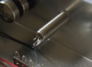
The Switchcraft jack has no markings for L, R or G. However, the L and R solder pins are of different heights. I copied the L & R wiring of the original jack from the manual and assumed that the same spot on the headphone plug will be applied to the Switchcraft jack. I have not tested this yet to confirm whether L&R are actually correct. The pictures of the rebuild thread provide a nice clean view of this.
The outside sheath of the jack is ground, although there is a little "hook" I assume is meant for soldering the ground wires. With the initial build I soldered everything to that hook, by soldering each item individually and then re-soldering the entire connection again at the end. It was quite a painstaking process getting all the resistor leads onto that little hook. It is not easily visible on the pictures, but you can identify the hook quite easily on the spec sheets.
With the rebuild, I decided to use a different approach and you can see that everything got soldered to the top of the sheath. Based on the wire routing, I soldered wires and resistors to both the left and the right of the sheath. Thus, one ground wire and one resistor soldered on the attentuator side of the sheath and another ground wire and another resistor to the other side. This was definitely much easier than the aforementioned way of connecting the resistors / wires.
I should note that the sheath is quite bendable. On the original build, it would bend almost every time I removed the top plate. With the rebuild, I find that to be less of an issue. Regarding the resistors, you only need 1/4 W, but I find that the 3W resistors add structural rigidity (if soldered as on the new build) to the sheath and I doubt the 1/4W resistor would add much rigidity.
Just use the kit resistors. I've used the 152B in another project, modified the ground tab/clamp by cutting off the end & drilling a small hole so it's more like a solder tab. Attached the diagram for the 152B. TRS Tip is the the shortest lug (Left channel).
Attachments
The coupling capacitors at the output of the Crack need to charge through something. If you leave these off, warm up your Crack, then plug in your headphones, expect to be purchasing new headphones.Nathan said:What's the purpose of running the tip and ring to ground, each via a 2.49k ohm resistor?
Nathan
New member
Caucasian Blackplate said:The coupling capacitors at the output of the Crack need to charge through something. If you leave these off, warm up your Crack, then plug in your headphones, expect to be purchasing new headphones.
If I had to choose between 2.4k ohm and 2.7k ohm resistors, which would one be best off using?
Nathan said:If I had to choose between 2.4k ohm and 2.7k ohm resistors, which would one be best off using?
2.4K.
-PB
Jeb Jeb
New member
Hi guys.
The switchcraft jack looks really nice for an upgrade further down the line! I have a rookie question, so bear with me. Here goes...
With the stock jack since it is plastic it is physically isolated from the plate then grounded via the wires, whereas the switchcraft 152 jack is metal so the sleeve connection is physically in contact/grounded via the plate as well as the wires too... right?
I also noticed that on the Neutrik locking jacks the sleeve connection is isolated from the panel/plate but there is a little screw that you can remove so as to ground via the panel too.
I just wondered about the what/why of all these grounding options, and whether it makes any difference at all with the Crack?
Thank you!
Jeb.
You are correct, it is not ideal. There are often such sacrifices when modifying our kits, though many go unrecognized.
Jeb Jeb
New member
Thanks PB, always appreciate your thoughts!
So I guess the best practice with the Neutrik locking jack would be to keep that little nylon spacer/screw in place to isolate sleeve from chassis, while with the switchcraft 152B you could use nylon shoulder washers to keep the jack isolated from the plate?
So I guess the best practice with the Neutrik locking jack would be to keep that little nylon spacer/screw in place to isolate sleeve from chassis, while with the switchcraft 152B you could use nylon shoulder washers to keep the jack isolated from the plate?
You'd have to find the right shoulder washer or grommet, then enlarge the hole, but yes, that would be a nice plan.Jeb Jeb said:while with the switchcraft 152B you could use nylon shoulder washers to keep the jack isolated from the plate?
Similar threads
- Replies
- 3
- Views
- 2K
- Replies
- 4
- Views
- 2K
- Replies
- 2
- Views
- 164