Submissive Mod

Adrian

New member
I wanted to add additional outputs to the Submissive Volume/Selector Switch so I would not have to change output cables or wire them in parallel.
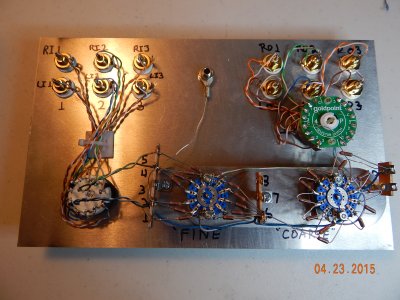
I added a 4-pole, 3-throw switch with two additional RCA output pairs.
I now have three inputs with a selector switch and three outputs with a selector switch.
I used a Goldpoint switch.  I may have been able to buy a less expensive switch from BH if available, but BH is not a parts store for stuff like this.
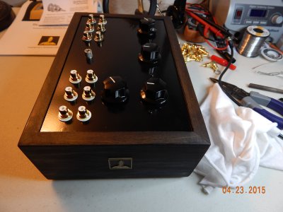
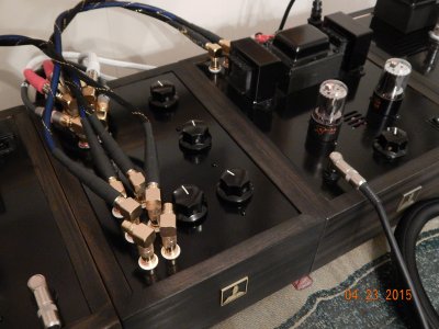
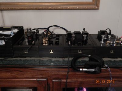
Here is the result.
 

Attachments

  • DSCN0694.JPG
    DSCN0694.JPG
    1.7 MB · Views: 432
  • DSCN0697.JPG
    DSCN0697.JPG
    1.7 MB · Views: 355
  • DSCN0700.JPG
    DSCN0700.JPG
    1.7 MB · Views: 319
  • DSCN0698.JPG
    DSCN0698.JPG
    1.7 MB · Views: 257
Hi adrian!

Thanks for your info on the submissive. I have a few more questions if that's ok.

First: I see that only two C sides are wired together in your switch, why is that?

Second: If I only wanted one input and 3 output, couldn't I just wire everything backwards? so the input first connects to the Fine -> then Coarse -->  the "output selector" (one that says 3e1 in your photo) to the 3RCA?

I kinda asked this before and DOC said:
"The submissive is by its passive nature a device with a relatively high output resistance (impedance). Thus it is not the best suited to plug multiple parallel loads into, which present a relatively low load. An active device with a lower output impedance would be better suited to the job. Or a switch could be installed that connects only one load at a time to the Submissive."

But I think my question was too ambiguous. I wanted to completely switch the wiring inside since the input selector itself is a switch correct? by choosing which input (1,2, or 3) you are effectively creating one pathway for the input to go through the fine then coarse and then to the one output on a stock submissive, if my understanding is correct?

 
  • In response to the "C Side" query:
    Because the switch is a 4-Pole switch, two of the poles are for the signal (left or right) and the other two poles are for the grounds for each channel.
    Looking at the photo, the top two are the signal (left on left and right on right) and the bottom two are for the ground (left on left and right on right).  That's just the way I decided to wire it and is arbitrary.  The ground jumper between the two bottom poles (the C sides you mention) is the common ground that goes to the original single pair of output RCA jacks.  This is the common ground for the entire unit going back to the center ground post.
    For the switch, the C is the common for each of the four poles - when you select position 1 the C in pole 1 is connected to terminal 1 pole 1.  You will notice there is a C in each of the four poles, so selecting position 1 will connect C and 1 in each of the 4 poles of the switch.  There is a left channel and ground and a right channel and ground making four poles.  Each pole (in my configuration) has three positions.

    Yes, you can wire the single original output RCA jacks as the input and the original input jacks as outputs from the selector switch.

    First, wire the three new output jacks to the selector switch per the manual.

    Second, wire the new single input jacks as follows:
    • For right (RED) input jack use green twisted pair and solder solid green wire to ground tab and white/green stripe wire to center pin. Connect other end of this green twisted pair to terminal strip 4L (solid green) and 5L (white/green stripe).  Solder 4L and 5L as directed in manual.
    • For left (BLACK) input jack use blue twisted pair and solder solid blue wire to ground tab and white/blue stripe to center pin.  Connect other end of this blue twisted pair to terminal strip 2L (solid blue) and 1L (white/blue stripe).  Solder 2L and 1L as directed per manual.

    This completes the new input wire changes.

    Third, wire the output to selector switch as follows:
    • Solder the drain wire (as shown on page 18) to terminal 10 and route to selector switch.  If you do not have enough bare drain wire to reach the switch, any single wire will work for this connection.  Solder the drain wire to selector switch center pins B and C.
    • Solder a single white/green stripe wire to the lower lug at the back of the coarse attentuator switch (as shown on page 21).  Route the other end to the selector switch and solder to center pin A.
      • Solder a single white/blue wire to the lower lug at the front of the coarse attentuator switch (as shown on page 21).  Route the other end to the selector switch and solder to center pin D.

      That should about do it.
 
PERFECT! Thank you so much! I will be doing this when I get the submissive. This is EXACTLY what I wanted. Thank you so much!!!! Seriously thank you for your time and explanations. Both you and Doc!
 
You're welcome.

It wasn't much work.
Before I put screw driver or solder iron to a project I thoroughly read the manual, make notes, AND markup or redraw the schematic with terminal numbers and notes.
This can make it easier for me IF I have to troubleshoot later.
For the Submissive, I developed a crude schematic (not complete) but enough to make it easier to trace the flowpaths and connections.

If Doc, PB, or Josh have the time, maybe they can provide a "peer check" to make sure I got it right.
 
Back
Top