hmbscott
New member
I have a Stereomour II on order. I have been eyeing the Bottlehead power amp lineup for some time now, and have been learning towards the Stereomour. The Black Friday sale pushed me over the edge. However, since I have a Moreplay preamp, I don't really need or want the integrated features of the Stereomour.
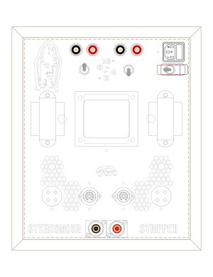
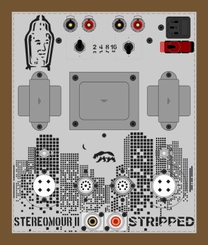
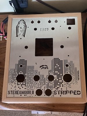
Therefore, I am planning to build it as a stripped down power amp with no volume, balance or selector features. Although, I do want to build in top surface output impedance switching. I will be designing and building a custom chassis plate to support the modifications.
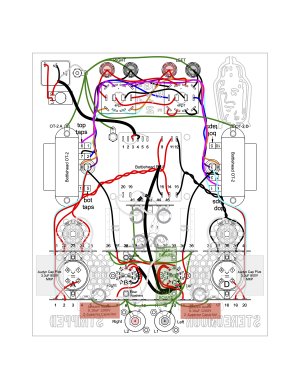
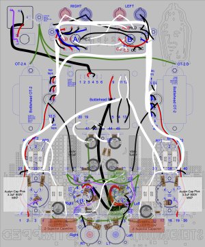
My calculations are that the input balance and volume pots should be replaced with a 20K/33K voltage divider. Another question, would changing the cathode resistor value from 365ohm to 360ohm be significant? I would like to change it to a Vishay naked z-foil resistor and that's the closest value I can find (see the input circuit diagram).
For output impedance switching of OT-2, I plan to use 4 DPDT switches, two of which are center-off (see the impedance switch circuit diagram).
Your review and critique will be much appreciated.
Thanks, Scott
Therefore, I am planning to build it as a stripped down power amp with no volume, balance or selector features. Although, I do want to build in top surface output impedance switching. I will be designing and building a custom chassis plate to support the modifications.
My calculations are that the input balance and volume pots should be replaced with a 20K/33K voltage divider. Another question, would changing the cathode resistor value from 365ohm to 360ohm be significant? I would like to change it to a Vishay naked z-foil resistor and that's the closest value I can find (see the input circuit diagram).
For output impedance switching of OT-2, I plan to use 4 DPDT switches, two of which are center-off (see the impedance switch circuit diagram).
Your review and critique will be much appreciated.
Thanks, Scott
") But, but in the process I can have lots of fun with some engineering creativity, and I can make it uniquely my own in the process.
But, but in the process I can have lots of fun with some engineering creativity, and I can make it uniquely my own in the process.