Stereomour Diagnosis Testing or Repair?

audiotecture

New member
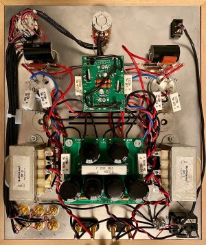
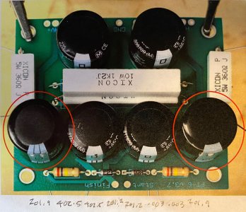
I ordered/purchased a Stereomour kit January 2013. I’ve successfully built and am using a Bottlehead Crack headphone amp. I finally “finished" my Stereomour kit today and made it through the resistance check fine. During the voltage test, I saw/smelled smoke so I unplugged the amp. I discovered that when I put the 2A3 tubes in for the voltage check I made the mistake of putting them in backward (I did not notice the different size pins and numbers). Reading about similar incidents on the Bottlehead forum it sounds like I may have damaged the tubes, resistors, etc. Rather than attempting to troubleshoot this myself, I thought I’d contact Bottlehead repairs to find out if I might be better off sending my Stereomour in for repair/diagnosis/testing rather than buying new tubes, new resistors, etc. not really knowing what the issue or issues might be. Doc B. suggested I post my issue on the forum in the hopes that Paul Birkeland or somebody else might be able to talk me through testing the transformer and other components to get a better idea of the amp's condition before I send it in for repair/troubleshooting.
 
I rechecked all of my resistance values and all matched the manual. I did a voltage check and all of the values matched the manual. I hooked up my turntable and I'm getting sound from the A-side binding posts but not the C-side binding posts. I also noticed that the PC-3 on the A-side is cool to the touch and the PC-3 on the C-side is hot to the touch. Although there no longer appears to be any smoke, there is a mild smell coming up through the vents when the amplifier is turned on. I've attached a photograph for reference, maybe you'll spot something.
 

Attachments

  • stereomour underside.jpg
    stereomour underside.jpg
    2.1 MB · Views: 26
Turn the amp off and let the power supply bleed down.  Measure the DC resistance between HV+ and pin 2 of the 4 pin socket on each side.

-PB
 
(keep in mind my real background is architecture & product design so audio/electronics is not an area of expertise) When I set my Fluke 117 multimeter to autorange, I get a reading of 586 ohms HV+ - C2 & 587 ohms HV+ to A2
 
Hey, there you go, you avoided a really expensive problem (toasted plate chokes).  What DC voltage do you get between ground and pins 1/4 on each 4 pin socket?
 
A1 = 58.4 V, A2 = 362 V, A3 = 0 V, A4 = 59.0 C1 = 59.99 V, C2 = 363.1 V, C3 = 0 V, C4 = 59.8
I'm assuming you wanted measurements with all three tubes installed and the amp turned on/powered up?
 
Yeah, those are working voltages.

The plate choke on the side where the tube wasn't inserted properly would've gotten burning hot, and it may need some time to cool off and forgive you. 

If the OA/OB voltages on the center PC board are within range, I would suggest listening to the amp.

On the tortured side, that 220uF/250V capacitor on the power supply board that feeds the "K" terminal was probably pretty angry, so you might consider replacing it in the near future.  Because your DC voltages look good, the cap hasn't catastrophically failed.
 
Thank you Paul. I'm going to play around with the speakers/speaker connections tomorrow early evenig (Eastern time zone) so I may discover something there that may be the issue (I also designed and built the speakers so there's a chance the issue is in the speakers at this point). Sounds like the amp and tubes may not be in as bad a shape as I thought so that's good news.
 
Paul,

I just ran a couple more tests and discovered two things that might be additional clues. The A side binding posts are sending a signal to one speaker the B side binding posts are not sending a signal to the other speaker. I thought this was odd since all of the readings tend to be symmetrical. I noticed that the readings at the rectifiers and the resistors on the large circuit board are not symmetrical (see image) testing from C side to A side I get readings of 201.9V (resister left), 402.5V (resister right), 402.5V (rectifier left), 201.2V (rectifier right), 201.2V (rectifier left), .003V (rectifier right), .003V (resister left), 201.9V (resister right). Something doesn't seem right about reading on the A side rectifier right and resister left? Any thougths?
 

Attachments

  • large circuit board readings.jpg
    large circuit board readings.jpg
    1.7 MB · Views: 23
What are the DC voltages on each of the 4 pin sockets?  If you have 200V coming out of one side of the power supply board, ALL of your DC voltages on one side of the amp will be incorrect.
 
Your power supply board is working.

The Stereomour will produce a little 60Hz hum at the binding posts, can you hear that on both channels?
 
OK, so there's an issue either with how the output transformer is hooked up on the tube side or the speaker side.  This could be missing or poorly soldered jumpers on the output transformer, poorly connected or missing wires from terminals 5 and 10 on that output transformer, a loose 3.3uF/630V capacitor, etc.
 
I went back and checked for missing wires (none that I could identify) and resoldered a number of connections in the areas that you described. Blew the fuse when I restarted the amp. The supplied fuse reads F1.5AL250V the manual reads 1.5A GMA slo-blo fuse. I'm having trouble tracking down replacement fuses online. It seems the supplied fuse and the fuse described in the manual are different fuse types? Can you clarify the proper fuse type and perhaps point me in the direction of an online source. Troubleshooting will need to wait until I get replacement fuses.
 
Back
Top