Speedball Voltage Check Issue [resolved]

M42

New member
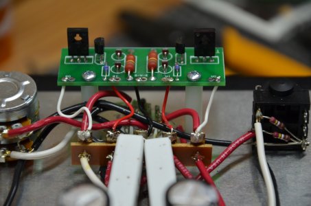
I am installing the small board for the Speedball upgrade. All the led's are illuminated, but I am getting a low voltage reading at OB. The indicated voltage is 11.12 volts instead of the anticipated 60 to 90 volts. The other readings are as follows:

OA  =  69.5 v

1A  =  232 v

B-A/B  =  0 v

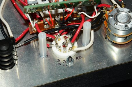
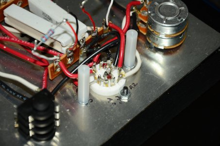
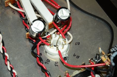
I have checked all my connections/solder joints and reheated what I thought might be suspect. I noticed that one of the led's on the nine pin socket was no longer illuminated (the one connected to A3 and the center terminal). Prior to the upgrade the amp always run dead silent, but during my last listening session with the amp I notice a low level hiss I'd not heard before. I'd forgotten about that before starting this project!

Would the failure of the socket led cause the voltage problems indicated at OB? I have done the chopstick test around the nine pin socket...the led does not light even intermittently. I know this issue should have been identified and dealt with in the first instance...my bad! Any advice would be appreciated.


Attachments

  • DSC_4817.JPG
    DSC_4817.JPG
    4.4 MB · Views: 106
You need to reheat all the solder joints on the MJE350 on the "B" side of that PCB, as the solder has not been allowed to flow properly.

Having used the chopstick test (intended to find noise issues usually), if you've poked the LED enough times, you can certainly break it.  If the LED is broken, OB voltage will be much higher than expected, and the voltage at A3 will settle to around 12V (and the LED will not be lit). Only if all three of these conditions are met should you consider the LED to be the issue.

(See page 20 in the manual for similar information)

-PB
 
Thanks for your reply Paul. I have reheated the MJE350 on the B side, the results are the same...I'm still getting 11 volts and the led on the tube socket does not light. The solder has wicked up around all three legs of the MJE350 from the bottom of the pcb.
 

Attachments

  • DSC_4812.JPG
    DSC_4812.JPG
    3.6 MB · Views: 76
Pop each wire out of OA and OB, then twist the board 180 degrees and reattach the wire from 5 to OA and the wire from 1 to OB, then recheck your voltages.
 
Is the white wire on the right side in the earlier picture properly attached to the tag strip? Insulation looks to just disappear into the hole.
 
I'm certain I have a good connection there. I'll reflow the joint again this evening. I failed to mention in the previous post that the led on the nine pin socket (at A3) still does not illuminate.
 
That's good information.  When you flipped the board around and the low voltage changed from OB to OA, that tells us that the small PC board is working.

As to why the issue is occurring in the first place, some potential causes are debris in or around the tube socket causing a short between pin A6 and A7 (or A6 and A5), what DC resistance do you get from terminal 5 to ground?

Also, to reiterate again, this is a problem that has nothing to do with the LED that isn't lighting.  If the LED was shorted out, terminal 5 would read something like 50V, and if the LED was open it would read around 170V. 
 
Measuring the resistance from the ground lug and terminal 5 the meter reads O.L the scale indicates M ohms. You will have to bear with me as the only reason I get these kits together are the outstanding build manuals. I know which end of the soldering iron gets hot....but beyond that............?
 
M42 said:
Ground lug to T5 is 2966 ohms
Yeah, now we are getting somewhere.  There are two 3,000 Ohm resistors in the amp, they connect to the 6080 back at the octal socket.  If, somehow, there is a miswire or a short back there, then sending a few mA of current through a 3,000 Ohm resistor will get you the weird voltage you have.

Did this Crack work before you put the Speedball in?
 
The amp has run without issue since I completed it about three years ago...it always ran dead silent. I had a chance to listen to it recently after it not being used for some time. It sounded great as usual, but as I was about to shut it off I did notice a low level hiss. I had not heard that before. I did not listen to it again before the upgrade kit arrived and forgot about it. As a result I didn't discover the led issue at the tube socket until then.

I have checked around the tube socket and find no debris which might be contributing to this problem.
 
I would pull the Speedball and put the resistors back. There's an issue with the underlying build that needs to be resolved first.
 
I reinstalled the two resistors. I could not find the identical value (22.1 kohm), I've used NTE 1/2 watt 22 k ohm, 2% in their place.

Resistance:                                        Voltages:

1    .378 m ohms                              91.5                     
2    .342 m ohms                              229
3    0                                                0
4    .329 m ohms                              228
5    1.06                                            26
6    2500                                          0
7    3050                                          26
8    0                                                26
9    2.95                                            0
10    2508                                          0
11    n/a                                            0                                         
12  0                                                0
13  .635 m ohms                              0
14  0                                                0
15  n/a                                            233
20  0                                                0
21    n/a                                            238
22  01.5                                          a1  26                                    b1    90.6
b3  2950                                          a2    0                                      b2    230
b6  2953                                          a3    1.45                                b3    26
rca ground jacks:                              a4    0                                      b4  26
ground lug    0                                  a5    0                                      b5  230
center pin    2502                              a6    90.7                                b6  0
                                                        a7    0                                      b7  0
                                                        a8    1.56                                b8  0
                                                        a9    0
 

Attachments

  • IMG_0155.JPG
    IMG_0155.JPG
    736 KB · Views: 51
M42 said:
5    1.06                                         
The amp should not be powered on again until we can determine what went wrong here.  Your last resistance reading was 3,000 Ohms, now it's 1 Ohm.  Neither resistance reading is correct.

I would be interested in seeing more photos of the build, as I might be able to spot the issue.

-PB
 
A few more photos of the amp...
 

Attachments

  • DSC_4831.JPG
    DSC_4831.JPG
    626.3 KB · Views: 37
  • DSC_4833.JPG
    DSC_4833.JPG
    3.8 MB · Views: 36
  • DSC_4834.JPG
    DSC_4834.JPG
    699.6 KB · Views: 32
  • DSC_4836.JPG
    DSC_4836.JPG
    3.7 MB · Views: 32
Back
Top