Speedball upgrade works only on right channel

tisun

New member
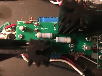
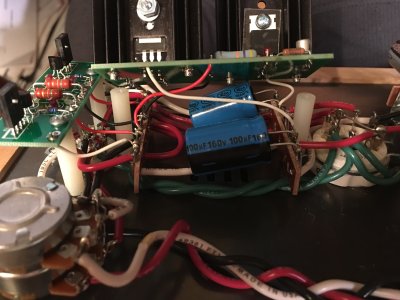
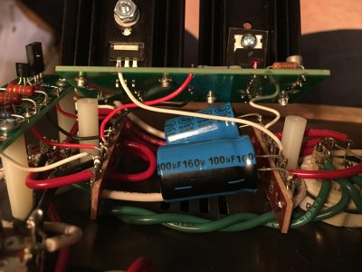
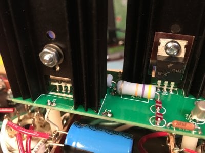
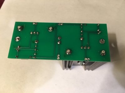
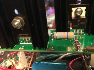
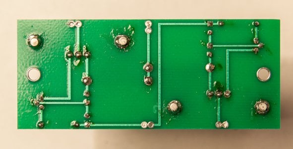
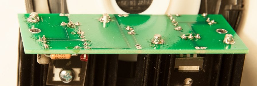
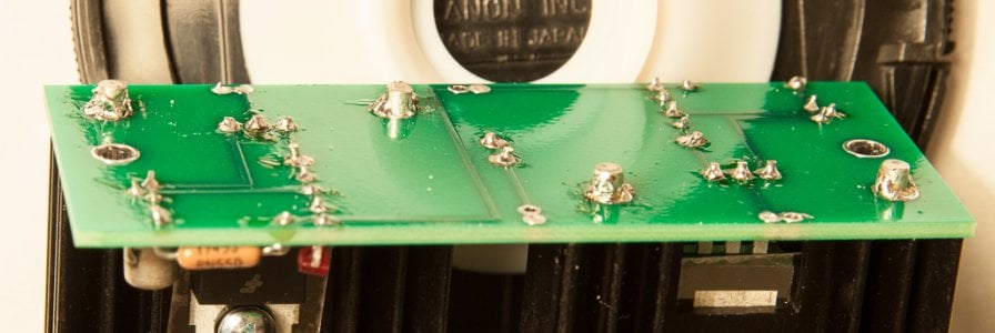
Crack 1.1 before Speedball works. Crack with the small circuit board of Speedball also works, passing voltage test and listening test. However, the adding the large circuit board doesn't pass voltage test, as showned below:

Terminal    Recommended  Measurement
                Voltage (DC)
OA            75-100V          112V
OB            75-100V          starts out at 147V then slowly decreases to 129V
G              0                      0
B+            170-195V          201V

All 4 LEDs are lit. Only the right channel has sound. When I remove the large circuit board and put back the 2 3KOhm 10W resistors, both right and left channels work again.

Did I do something wrong?


Attachments

  • 2018-06-28_21-15-42.JPG
    2018-06-28_21-15-42.JPG
    1.7 MB · Views: 15
  • 2018-06-28_21-24-30.JPG
    2018-06-28_21-24-30.JPG
    1.9 MB · Views: 19
  • 2018-06-28_21-23-50.JPG
    2018-06-28_21-23-50.JPG
    2 MB · Views: 17
From what little I can see of the bottom of the big PC board, I would recommend taking it out and reheating all of the solder joints, especially those on the TIP50C.  The TIP50 will take heat from a soldering iron for a considerable amount of time before taking damage, so apply your iron to each solder pad/lead, flow a tiny bit of extra solder, then count to five. 

The MJE350 transistors on the small PC board don't sink heat quite as well and aren't mounted to heatsinks, so they are a little easier to work with.
 
I reflowed all the solder joints on the big board. It took a lot of heat to get solder to the middle pins of the TIP50 transistors, but I managed to do it (see the first photo). However, voltage test remains the same. The second photo show the bottle of the circuit board before I redid all the joints.
 

Attachments

  • IMG_0793.JPG
    IMG_0793.JPG
    1.7 MB · Views: 22
  • IMG_0783.JPG
    IMG_0783.JPG
    1.3 MB · Views: 21
Even more? Wow. I think I already spent a minute heating the center pin at either 650 or 800 degree. Alright, I will it another shot.
 
More heat, more solder at T50 pins. Voltages still don't make sense:

OA 77V
OB 127V
G 0V
B+ 126V

The heat sink for Q2A is quite hot to the touch, while the one for Q2B is cool.
 
Could you pop off the board and take some photos of the bottom?  To confirm, the voltages on the small board are still OK?
 
The voltages of the small board, without the big board and with 3K Ohm resistors re-attached, are still normal:

OA      74V
IA      173V
B-A/B    0V
IB      173V
OB      73V

Terminals:
6      0V
7  101V
8      0V
9    101V
10    0V
 

Attachments

  • 20180630_1812.jpg
    20180630_1812.jpg
    336.2 KB · Views: 12
  • 20180630_1814.jpg
    20180630_1814.jpg
    210.4 KB · Views: 8
  • 20180630_1815.jpg
    20180630_1815.jpg
    222.2 KB · Views: 8
  • 20180630_1813.jpg
    20180630_1813.jpg
    194.6 KB · Views: 8
However, with the big board attached, the voltages of the small board take on the (odd) corresponding values of the big board.
 
Without 6080, voltages on big board are

OA - 0V
OB - rolling from 34V to 161V, repeat
G - 0V
B+ - 222V

voltages on small board:
OA - 71V
IA - 222V
A/B - 0V
IB - 222V
OB - 71V

For reference, with 6080 in the socket, big board's voltages:

OA - 76V
OB - starts from 136V and drops to 119V
G - 0V
B+ - 121V

small board:
OA - 72V
IA - 126V
A/B - 0V
IB - 121V
OB - 72V
 
Hmm, half the board is certainly misbehaving.  I would recommend contacting replacementparts(at)bottlehead(dot)com regarding this issue.  Be sure to provide your name and a link to this post.  I would recommend replacing the TIP50 and 2N2222 transistor on the offending side of the larger board.
 
Back
Top