Speedball Upgrade - Fail Voltage Check

raps1514

New member
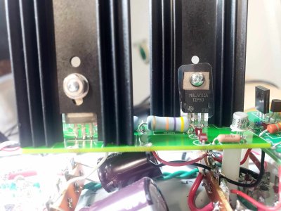
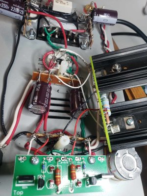
Hello - back again. After a successful Small Board assembly and install, I attempted the Large Board and started having issues with the voltage check. The amp starting emitting a smell and got quite hot around transformer.
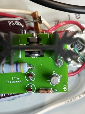
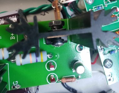
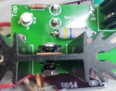
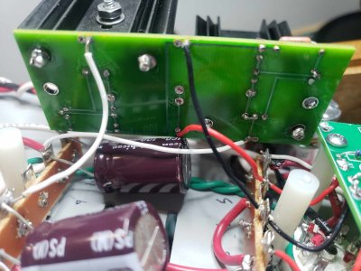
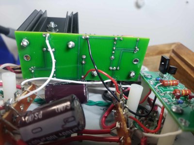
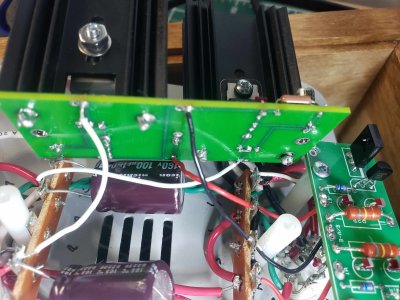
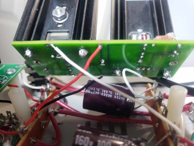
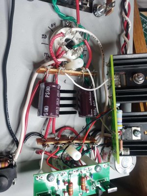
Large Board:

OA: 3.4V
OB: 41V
G: 0V (but kinda fluctuates)
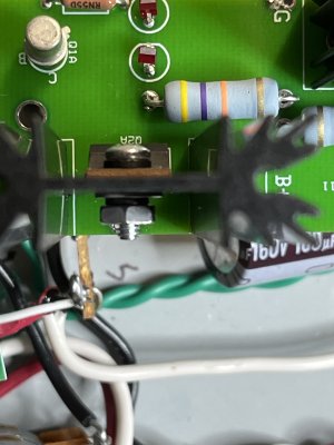
B+: 45V

Thanks for any help!
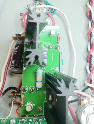
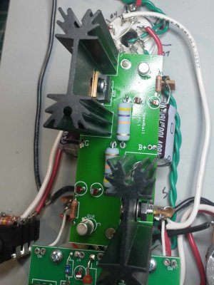
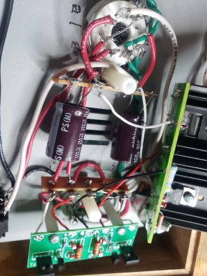
 
The problem you're having most often happens when the hardware is not properly installed on the TIP50 transistors.  If the insulating pads and shoulder washers are not properly placed, the metal tap of the TIP50 will touch the heatsink and cause this problem.  Please double check that.
 
Double checked the metal tab of the TIP50 and it is not touching the heatsinks; the insulating pads is buffering. (I'm pretty sure.)

FWIW - Big Board is reading with 6080 still removed:

OA: 2.14V
OB: 1.536V
G: 0.3V
 

Attachments

  • IMG_1308.jpg
    IMG_1308.jpg
    517.9 KB · Views: 29
  • IMG_1309.jpg
    IMG_1309.jpg
    521.5 KB · Views: 25
To me it looks like the screw touches the metal on TIP50. There should be an insulating washer between.
But maybe it's just the picture.
 
I agree, I cannot see the insulating washer.  Review the warning on the bottom half of page 22 and the instructions that follow...
 
Still not quite seeing what y'all are seeing. Here are more photos.
 

Attachments

  • 381309070_866989451093412_3584140644083812953_n.jpg
    381309070_866989451093412_3584140644083812953_n.jpg
    141.6 KB · Views: 16
  • 381288713_6338627942933511_4440846384024573574_n.jpg
    381288713_6338627942933511_4440846384024573574_n.jpg
    169.8 KB · Views: 14
  • 381279367_288441897270605_9183747256167262463_n.jpg
    381279367_288441897270605_9183747256167262463_n.jpg
    171.1 KB · Views: 12
  • 381288710_1046822103010665_651647173284877509_n.jpg
    381288710_1046822103010665_651647173284877509_n.jpg
    156.8 KB · Views: 15
  • 381279355_616279100434284_1847962558757487692_n.jpg
    381279355_616279100434284_1847962558757487692_n.jpg
    146.6 KB · Views: 17
The black shoulder washer should be under the screw head on both heat sinks. You have it on the wrong side - under the nut - on Q2B rather than under the screw head. So the screw on that side is touching the tab on the transistor, which it must not do. You need to take the assembly apart and reinsert the black washer from the other side of the heat sink, so the shoulder of the black washer is on the screw head side.
 
I've gone ahead and attempted this again. Sending two pics showing the placement of the parts, unscrewed in. And another two pics with them screwed in. Note - they look very similar to previous pics because...I'm still not sure what I'm doing wrong.

Also - the LEDs on the small board do not light, nor the ones on the Q2B side. The ones are very well lit, however.
 

Attachments

  • IMG_1312.jpg
    IMG_1312.jpg
    1.7 MB · Views: 8
  • IMG_1311.jpg
    IMG_1311.jpg
    1.8 MB · Views: 12
  • 383087295_208855185538566_1838846331400537116_n.jpg
    383087295_208855185538566_1838846331400537116_n.jpg
    118.3 KB · Views: 13
  • 381427109_823779222826533_5772387384519223025_n.jpg
    381427109_823779222826533_5772387384519223025_n.jpg
    87.5 KB · Views: 16
Looks right now, as I can see the shoulder washer is under the screw head on Q2B. Couldn't see it for sure before.
 
Still getting the same resistance and failing voltage checks. Slight chemical-type smell coming from top of chassis. LEDs not lighting up on Q2B side.
 
Next I would suggest removing the large Speedball board and taking pictures of the soldering on the bottom, as well as the build of the stock kit that's under the big Speedball board.  The chemical smell that you are smelling is your amp responding to the near dead short that your large Speedball board is presenting, so don't run it too long and let it cool between tests.
 
My undercarriage handiwork.


Attachments

  • 1.jpg
    1.jpg
    175.5 KB · Views: 17
  • 2.jpg
    2.jpg
    159.2 KB · Views: 16
  • 3.jpg
    3.jpg
    199.9 KB · Views: 11
  • 4.jpg
    4.jpg
    162.4 KB · Views: 9
  • 5.jpg
    5.jpg
    274.8 KB · Views: 7
  • 6.jpg
    6.jpg
    271.3 KB · Views: 5
  • 7.jpg
    7.jpg
    204.1 KB · Views: 6
Two of the pins of a TIP50 are soldered together.  This can turn a transistor into a diode and burn up your amp.  Definitely make sure no other pairs of pins are touching and clip those down so they can't touch.
 
Back
Top