So, I finished the setup of the Crack, and once I plugged in the power source everything was normal. However, once I check terminal 3's voltage a small spark went off. Did the terminal spark because of my testing method or did I solder something incorrectly? I check all the soldering connections and they all seemed good with no incomplete joints. What should I do next?
You are using an out of date browser. It may not display this or other websites correctly.
You should upgrade or use an alternative browser.
You should upgrade or use an alternative browser.
Spark while voltage testing
- Thread starter Krishk
- Start date
kgoss said:Did you pas the resistance tests?
A spark usually means you touched 2 terminals with the meter probe.
I use a clip lead for the ground connection so I can concentrate on the measurement point.
Yes I passed all the resistance tests. I have a clip for the ground as well but my hands are so shaky with the other lead probe, so I am betting I did touch two terminals. Did I ruin my kit? I rechecked all the resistances and everything was in a normal range.
Would it be harmful if I assume I pass the voltage tests due to passing the resistance test and plug in a pair of headphones?kgoss said:Did you pas the resistance tests?
A spark usually means you touched 2 terminals with the meter probe.
I use a clip lead for the ground connection so I can concentrate on the measurement point.
Paul Joppa
Moderator
Yes that is risky. PB will probably step in, but meanwhile just re-do the voltage checks (being extra careful about touching the terminals). Better yet, use clipleads for both terminals, turning the preamp off when moving the clips. It takes longer, but has a much better chance of getting clean data without accidental shorts.
BTW, I sympathize with the shaky hands, I have that too.
BTW, I sympathize with the shaky hands, I have that too.
That's a really good idea I'll definitely try that. Do you think I damaged my amp in anyway with the previous sparking? I rechecked the resistances and they all came back normal again.Paul Joppa said:Yes that is risky. PB will probably step in, but meanwhile just re-do the voltage checks (being extra careful about touching the terminals). Better yet, use clipleads for both terminals, turning the preamp off when moving the clips. It takes longer, but has a much better chance of getting clean data without accidental shorts.
BTW, I sympathize with the shaky hands, I have that too.
Paul Joppa
Moderator
Maybe, maybe not. I'm not the Crack expert :^) But the only way to know for sure is to do the resistance checks (which you did) and then do the voltage checks.
D
Deke609
Guest
Krishk said:Do you think I damaged my amp in anyway with the previous sparking? I rechecked the resistances and they all came back normal again.
As PJ said, you really can't tell until you do the voltages tests - that's real test for whether you have a working amplifier. There's more than a fair chance that the spark failed to cause any real damage - and if if something is damaged it will almost certainly be cheap to replace. The only pricey stuff in the amp is the transformer and the tubes, and i can't imagine a momentary spark doing them in.
Following up on PJ's recommendation, i suggest you get some alligator and mini-hook test leads. AmZon sells sets of test leads for under $15. I use mini-hooks almost exclusively. The hooks are small, so it would be very difficult to connect two difference points and cause a spark. And they grab onto the target terminal or wire really well. And in the occasional circumstance where they pop off the terminal you are measuring, an internal spring instantly retracts the hook: no accidental contacts.
cheers, Derek
A spark at terminal 3 with your other probe at terminal 12 doesn't really say a lot about what the voltages might be. Having that happen and then plugging in headphones and using the amp is not a wise course of action.
Take a piece of tape and wrap the metal tip of your red probe so that only the very end of it is exposed. That will help to avoid touching terminals you don't want to touch when you probe around in the circuit. Then redo your voltages measurements. They will most likely be fine.
Ok, so I got some hook leads and I tried to do the voltage testing again but the tube leds weren't lighting up however they were lighting up before. I checked all the soldering connections and everything was fine. Is it possible that I blew the fuse? If so how would I get a replacement?
Also, when I check to see which tube is glowing, only the 6080 is glowing where the 12AU78 does not.Krishk said:Ok, so I got some hook leads and I tried to do the voltage testing again but the tube leds weren't lighting up however they were lighting up before. I checked all the soldering connections and everything was fine. Is it possible that I blew the fuse? If so how would I get a replacement?
Could you post the DC voltages you get on terminals 1 through 10?
If the 6080 lights up and the 12AU7 does not, the green twisted wiring going from the 8 pin socket to the 12AU7 may be loose at either end. Do remember that the 12AU7 doesn't glow particularly brightly.
-PB
If the 6080 lights up and the 12AU7 does not, the green twisted wiring going from the 8 pin socket to the 12AU7 may be loose at either end. Do remember that the 12AU7 doesn't glow particularly brightly.
-PB
Hi so my voltage tests results arePaul Birkeland said:Could you post the DC voltages you get on terminals 1 through 10?
If the 6080 lights up and the 12AU7 does not, the green twisted wiring going from the 8 pin socket to the 12AU7 may be loose at either end. Do remember that the 12AU7 doesn't glow particularly brightly.
-PB
Terminal 1: 170 Volts
Terminal 2: 190 volts
Terminal 3: 0 volts
Terminal 4: 190 volts
Terminal 5: 170 volts
Terminal 6: 0 volts
Terminal 7: 170 volts
Terminal 8: 0 volts
Terminal 9: 170 volts
Terminal 10: 0 volts
Just to reiterate, the leds and the 12au7 are no longer lighting up. However, yesterday before I sparked terminal 3 the leds and the 12au7 tuber were both lighting up.
Once again thanks for the help, I'm a bit of an amateur when it comes to electrical wiring so the help is greatly appreciated.
D
Deke609
Guest
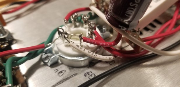
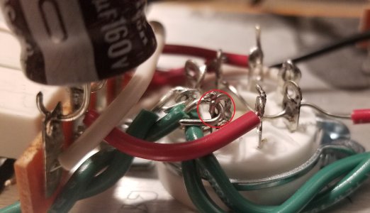
Hi Krishk - I'd follow PB's advice here and really scrutinize the green heater wiring that runs between the two tube sockets.
No 12AU7 glow suggests that there's no heater current, and the green wires carry that current directly from the transformer. And you know that the heater winding of the transformer is working b/c the 6080 glows. So all of this points to a possible faulty joint on the green wires between tube sockets. The problem might turn out to be somewhere else, but this is the first thing you need to rule in or out.
It might be helpful if you posted clear pics of each socket and of the solder connections of the green wires at each socket.
cheers, Derek
Paul Birkeland said:... the green twisted wiring going from the 8 pin socket to the 12AU7 may be loose at either end.
No 12AU7 glow suggests that there's no heater current, and the green wires carry that current directly from the transformer. And you know that the heater winding of the transformer is working b/c the 6080 glows. So all of this points to a possible faulty joint on the green wires between tube sockets. The problem might turn out to be somewhere else, but this is the first thing you need to rule in or out.
It might be helpful if you posted clear pics of each socket and of the solder connections of the green wires at each socket.
cheers, Derek
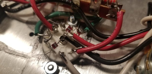
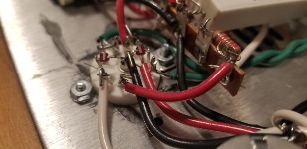
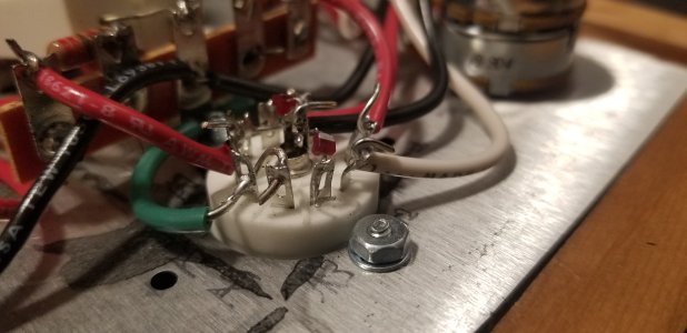
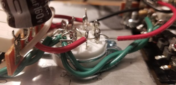
I've attached pics of the tube sockets. Please let me know if you need better pictures. I checked all the solder joints and they all seem stable however, please let me know what you think.Deke609 said:Hi Krishk - I'd follow PB's advice here and really scrutinize the green heater wiring that runs between the two tube sockets.
No 12AU7 glow suggests that there's no heater current, and the green wires carry that current directly from the transformer. And you know that the heater winding of the transformer is working b/c the 6080 glows. So all of this points to a possible faulty joint on the green wires between tube sockets. The problem might turn out to be somewhere else, but this is the first thing you need to rule in or out.
It might be helpful if you posted clear pics of each socket and of the solder connections of the green wires at each socket.
cheers, Derek
Attachments
Similar threads
- Replies
- 9
- Views
- 6K
- Replies
- 2
- Views
- 2K
- Replies
- 4
- Views
- 888