Smashup Voltage [resolved]

1026mind

New member
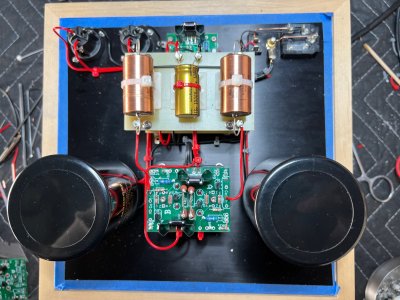
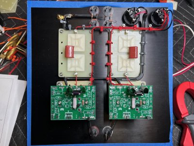
I had built the smash a few years back and it worked fine, well the usual noise and microphonic. So I decided to do the smashup upgrade and to build it on two chassis , one the power source and the voltage regulators and the rest on the second chassie .
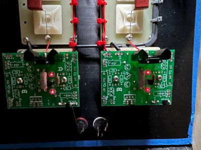
I finished the power supply but I am getting different  voltages
B1-0v
B2-212v
B3-1.847v
B4-0v
B5-212v
B6-1.847

Please help!!
Thank you!
 
I would post build photos if you can.  I haven't provided tech support on a Smash-up in some time, so a visual inspection is a good place to start. 

On the surface, I see the same issue on both sides, so it's likely that the same mistake made it onto both boards or into the build on both sides.

The 1.8V on the cathodes means the 6SN7 triodes are sucking down a ton of current.

What are your OB voltages on each PC board?  If for some reason the 4P1L tubes aren't drawing any current, that could possibly cause some of the issues you're experiencing.
 
The 4P1L are not in place, I only completed the power supply and the voltage regulators . The OB voltages are the same with B2 and B5.
 

Attachments

  • IMG_0095.jpg
    IMG_0095.jpg
    995.8 KB · Views: 19
If you don't have the 4P1L tubes drawing the appropriate current, it won't really be possible to ascertain whether there's any issue that needs to be resolved at this juncture.

 
I completed the second part, the voltages are:
B1 - 0V
B2 - 208.5V
B3 - 9.92V
B4 - 0V
B5 - 107.5V
B6 - 1.835V

IA - 210V Both sides
OB - 62V Both sides
 

Attachments

  • IMG_0097.jpg
    IMG_0097.jpg
    1.1 MB · Views: 8
Well I would check to be sure that the Kreg cathode connections are connected to the appropriate plates at the regulator tube.  If you have plate A and cathode B hooked up to the same high voltage regulator, then you can get weird problems like this, and this is a pretty common problem with highly customized builds like this.
 
they go to B3/kreg and B6/kreg for the cathodes and B2/OB, B5/OB for the plates.
the voltages where the same in the power source for both sides before I build the second part
 
I would next be looking for things like backwards LEDs or any transistor/431 device that has continuity between any pairs of legs.
 
I'm not sure what other help to offer.  Since your build deviates rather substantially from the kit we provide, the amount of help I can provide is a bit decreased. 

What jumpers did you install on the regulator board?
 
OB to +reg to Breg
-reg to bA
so if I disconnect the power source and measure voltage at !50V L and !50V R I get 212V, after I connect to the rest I get 107.5 and 208.5?????
I really appreciate your help
 
The presence of a high Kreg voltage on one side of the regulator suggests that side should work.  The low Kreg on the other regulator suggest that side would not.

Do your jumpers leaving OB go to Breg and +Reg on the B side or the A side?
 
The Ob jumpers where wrong, they where going from left side to right, rewired and the voltages are in line now.
THANK YOU VERY MUCH!!!
 
Back
Top