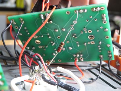
I know this isn't the most helpful suggestion, but honestly I would go back over each individual step in building and installing that PC board.
Actually, it probably is the most helpful suggestion. But I want to make sure I understand correctly - go over each step means to check, or to physically rebuild? If you mean checking each component, in order of installation, I will do that first.
And if that doesn't go anywhere, I am actually ready to rebuild this section from scratch, assuming it wouldn't cost a fortune. I know you said that a new board wouldn't necessarily solve the problem, but what about a new board and replacing most of the components? I assume that any resistors which check out can be considered undamaged, but I did wonder about transistors. (And I don't know how to check them either.)
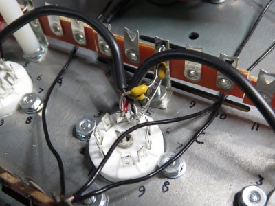
If, for example, I can just replace some or all of those components for the shunt regulator and install them on a new board, using new wire for all the connections, I'd rather spend a little money (within reason) on that, because as long as the power supply section shows no problems when I retest it, the rebuild of the board with new components ought to resolve the issue. Can I safely assume it's nothing to do with the tube? Or the socket?
I'm far from considering sending it in, because it's not even one-third built yet, so there aren't that many steps to retrace. Concerning new components, if I do that it would be more convenient for me to put together an order through Mouser or Digikey in Japan - are there any particular pitfalls versus getting replacement parts from Bottlehead?