Screwed up my Crack upgrade

flyfisher55

New member
Crack was working fine and then I finally got around to installing the Speedball upgrade.
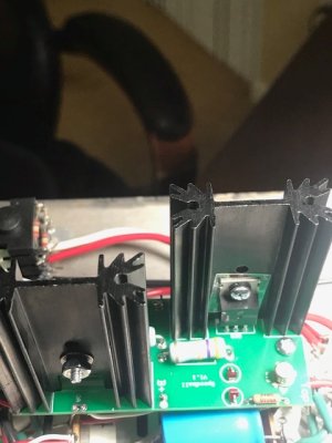
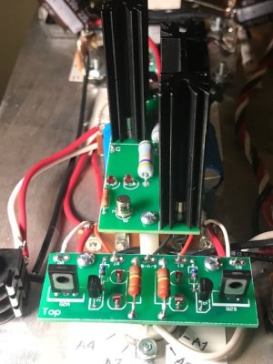
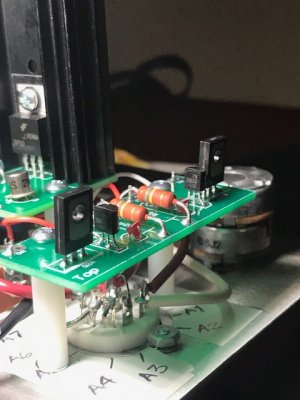
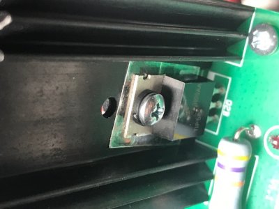
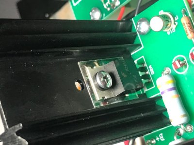
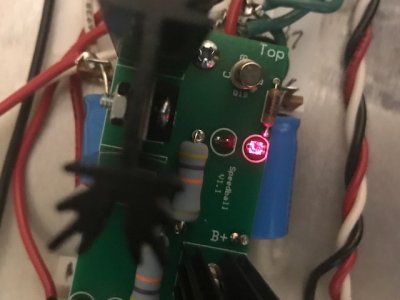
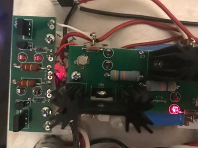
Everything was good right up to the very end. I was checking voltage on OA and I let the probe slip in. I'm pretty sure I touched one of the TIP-50 legs. I heard a small 'zap' and the two Led's on the left went out.
What next?
 
I need to clarify a couple of things... When I said two LED's on left went out  I was referring to the two LED's directly behind the transistor and next to G terminal. The B side?

Prior to this all appeared to be working correctly. Resistance passed and stage one of the upgrade passed all test within parameters. I am a total newly to this and have bad eyesight to boot. Hope I can get some help from those of you in the know. Thanks in advance
 
small board
OA-51.5
1A-90.1
B-A/B-0V
1B-90
OB-53.7

Large Board
OA-99
OB-50.6
G-0
B+-90
Two LED's directly below 1B on small board are also out
 
Your tip50 transistors are likely not properly mounted.  Do not run your amp until this is remedied, as you're likely to burn up the 270 ohm resistors in the power supply.

One way to check on this is to pull the 6080 and run the amp without it.  If the IA/IB voltages on the small PC board pop back up closer to 200V, that tends to confirm that the TIP50 transistors aren't mounted properly.  Also use this test to check the OA/OB voltages on the small board to be sure they are appropriate (seeing 50V at OA or OB would make me suggest checking whether one or more of the PN2907 transistors is in backwards).

You can also post photos of your build if you aren't sure one way or the other.
 
The fact that all LED's were lit prior to my slip where I allowed the red probe to short out against the TIP50 and heard the zap which at that very moment resulted in the LED's going out has no relevance?
 
I removed 6050 and these are my results on small board
IA-227
IB-227
OA-68
OB-81
 

Attachments

  • IMG_6488.jpg
    IMG_6488.jpg
    75.3 KB · Views: 21
  • IMG_6486.jpg
    IMG_6486.jpg
    99.2 KB · Views: 26
  • IMG_6490.jpg
    IMG_6490.jpg
    86.6 KB · Views: 27
Could I see a close shot of each TIP50?

Your numbers are consistent with a shoulder washer not properly placed on at least one of the TIP50 transistors.
 
This shows LED's out. Note all were lit prior to my accident
 

Attachments

  • IMG_6510.jpg
    IMG_6510.jpg
    82.3 KB · Views: 35
  • IMG_6511.jpg
    IMG_6511.jpg
    61.5 KB · Views: 27
  • IMG_6512.jpg
    IMG_6512.jpg
    73.1 KB · Views: 22
Are both LEDs on the 9 pin socket illuminating?

The small PC board should still work fine regardless of what you've done to the large board, so it's unusual that it doesn't appear to be (and even more unusual that the OB voltage is within range).
 
Both LED's on 9 pin socket are lit. One on large board and two on small board.
I read the instructions and specifically what is said about LED's on page 31. As I said previously all were lit until I slipped with the positive probe and touched the Tip 50 and heard the zap. Immediately after that the LED's went out. Prior to that the small board passed ALL test.
 
The next step would be to just remove the large PC board, then run the amp again with just the 12AU7 and the small board.

With the big board out, you can set your meter to DC resistance and measure between each pair of legs on each TIP50 and each 2N2222 transistor.  You will likely find that some pairs of legs are shorted together, indicating that a transistor needs to be replaced. 

Since the TIP50 transistors were properly mounted and working at some point, it's totally possible that both the TIP50 and 2N2222 where you had your slip are now shorted (thus providing a ground reference on the collector of the TIP50).

With the big board out, we can focus on restoring proper operation to the small PCB.

-PB
 
I removed the large board and what to make sure I do this correctly. I am measuring DC resistance by Ohm setting on my multi meter?
 
Turned amp on with 12AU7 after removing large board. Two LED's under 1B are still out. I'm going to need a bit of guidance doing the resistance test on the large board. As I said previously, "total newby" Sorry!  :-[
 
Yes, you can run the amp with no 6080 and no 3K resistors.  Yes to DC resistance, set it to the lowest range if your meter isn't auto ranging.

You'll want to do the same test for shorts on the transistors on the small board as well.  It is highly unusual to have that kind of failure from a slip at one of the outputs on the big board.
 
DC VOLTS OA 68.2
                IA 233.6
                B A/B 0
                IB 233.6
                OB 82.4
 
Back
Top