Resistance Checks help

deltaray

New member
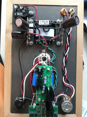
So I just completed my Crack and I'm a bit clueless on the resistance checks. I'm not entirely sure I'm doing it right.

So here are the measurements

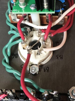
Terminal      Resistance      Measured

1          *          *
2          *          *
3          0 ohms          0 ohms
4          *          *
5          *          *
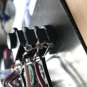
6          0 ohms      unstable number, starts out at 30 ohm and value slowly decreases
7          2.9K ohms      2.9k ohms
8          0 ohms          0 ohms
9          2.9K ohms      2.9K ohms
10        0 ohms        1.2K ohms
12        0 ohms          0 ohms
13        *          *
14        0 ohms          0 ohms
20        0 ohms          0 ohms
22          0 ohms              0 ohms

B3        2.9K ohms      2.9K ohms
B6        2.9K ohms      2.9K ohms

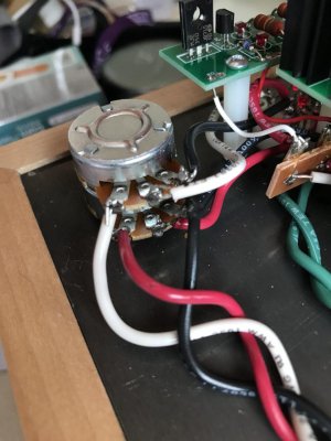
RCA jacks:    (not entirely sure where to place the dmm pins)
Ground lug        0 ohms        ??
Center pin        90K ohms—100K ohms  ???

However I did try the crack out with headphones and found no issue with the sound. Is this too dangerous?
 
Was your Crack purchased recently?  (is the file name for the manual Crack 1-1?)

The resistances at 6 and 10 would prevent me from using it or powering it up.  There is a wire from 6 to the headphone jack and a wire from 10 to the headphone jack.  Without headphones plugged in, these wires are shorted to ground through the headphone jack (in the 1-1 version of the manual).  For you to get the resistance values that you see, these connections are not properly being made, and it's likely that there is a connection issue at the headphone jack itself.
 
Yes, the manual is the "Crack 1.1 Manual".

I see, then it could be that i'm performing the tests wrongly. This because i'm able to power it up, listen to music through my 6xx. I don't notice any hum and stereo imaging is fine.

puzzling though.. is there any place where i can refer to on how the resistance voltage check are to be properly done?
 
Since nearly all of your resistances were in spec, this is not an issue with how you're measuring the resistances.

The resistance failures do indicate a potential safety problem though, how are the solder joints on your headphone jack?
 
For the ground lug and centre pin, where do i place the pins at for the testing?

Below are the pictures of the solder work of the headphone jack.
 

Attachments

  • IMG_6064.JPG
    IMG_6064.JPG
    1 MB · Views: 26
  • IMG_6065.JPG
    IMG_6065.JPG
    773.6 KB · Views: 27
  • IMG_6066.JPG
    IMG_6066.JPG
    731.4 KB · Views: 30
There is very little solder on any of these terminals. Add some more and leave the iron on until it flows out. You don't need to fill the holes but if that does happen it's no problem. Solder should be shiny with a smooth shape.
 
Thanks for the guidance. Added more solder to those joints. Now able to pass the resistance and voltage tests.

I however now noticing channel imbalance on the left side. I didn't do anything to the potentiometer, any places I should look at?

edit: this is me cranking the volume to near full and dropping the output volume. there is sound from both sides but the left side is noticeably more.

edit2: also should this bother me, given that I intend to do a speedball upgrade soon which may impact the LR channels anyway?
 
Always best to leave the SB fitment until the Crack is working correctly and reliably. I would also politely say that if the headphone jack soldering is consistent with the rest of the build, it would be a good idea to check and correct/reflow all of the other connections. That may well cure the imbalance you are now reporting.
 
Can you post your voltages?

Given the small snippet of photos you provided, I would suggest that your low channel may be caused by a flaky solder joint.
 
Really appreciate your help in diagnosing the issues.

The voltages are as follows
1. 85V
2. 186V
3. 0.7V
4. 186V
5. 81V

6. 0.3V
7. 117V
8. 0.6V
9. 111V
10. 0.3V
 
Which terminal are you using as ground for your meter probe?

0.3V DC is pretty low, but may indicate that you have a solder joint along the ground buss that isn't quite doing its job all the way.

-PB
 
That would be 12U per the manual right?

I’m attaching crocodile clips to the meters probes and then to these terminals.

Which terminals and joints should I check out in particular?
 
I see it now, so that bare buss wire through the hole of the safety ground lug needs to be completely soldered through.

Thank you!
 
Alright, have check and resoldered the joints joint along the ground buss. 

The voltages remeasured are as follows
1. 85V
2. 184V
3. 0.5V
4. 184V
5. 81V

6. 0.4V
7. 116V
8. 0.7V
9. 111V
10. 0.3V

Doesn't seem like there is much change in the measurement.
 
Having difficulties putting the images up on the forum, tried 5-6 times.

Anyway follow this link for the build images
https://imgur.com/a/pAJfeoO
 
1.  Your UF4007 diode bridge scares me a little.  The instructions in the manual are extremely specific, I would revisit that a little bit.
2.  13U could use more solder.
3.  3L is not all the way soldered.
4.  B1 and B4 don't look all the way soldered.
5.  2U is poorly soldered.
 
ok revisited the points you addressed. actually added the speedball upgrade.

There is still a imbalance leaning towards the left. tracks where guitar is clear right, now appear in the middle.

is the similar problems with either the tubes or pots? looking up the other threads.

I've added the pictures now, do let me know if you need more images.

OA - 76.1V
OB - 71V < is the voltage here suppose to match OA?
G - 0.6V
B+ - 196V
 

Attachments

  • photo_2018-09-30_16-36-09.jpg
    photo_2018-09-30_16-36-09.jpg
    171 KB · Views: 18
  • photo_2018-09-30_16-36-02.jpg
    photo_2018-09-30_16-36-02.jpg
    118.1 KB · Views: 13
  • photo_2018-09-30_16-35-59.jpg
    photo_2018-09-30_16-35-59.jpg
    99.1 KB · Views: 14
  • photo_2018-09-30_16-35-52.jpg
    photo_2018-09-30_16-35-52.jpg
    159 KB · Views: 12
  • photo_2018-09-30_16-36-04.jpg
    photo_2018-09-30_16-36-04.jpg
    145.5 KB · Views: 15
  • photo_2018-09-30_16-36-06.jpg
    photo_2018-09-30_16-36-06.jpg
    127.3 KB · Views: 15
Back
Top