Resistance and power issues.

pvannest

Member
I just completed my mainline and have a few issues.  Note, this is my 4th kit.

First off the resistance I get from 12, 14, 17, 24, 27, 29 are all nothing.  Not one of them is really connected to anything let alone any form of capacitor.  The rest of the resistance checks are in parameters.

On the voltage side of things, I have the following.
+275 vDC, I have 265
+6.3 vDC, I have 5.6,  not anywhere near 55-65 Volts
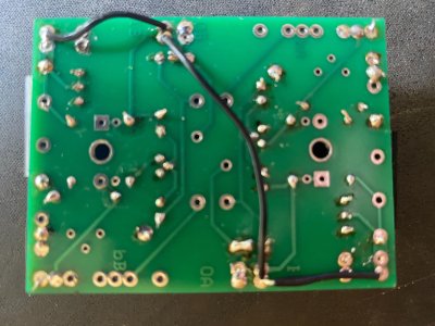
-6.3 vDC,  On the left I am reading, 5.9 Volts DC on the left side and I am reading.  .65 Volts on the left.    I will be resoldering both of the leads from the power supply and see what happens there.

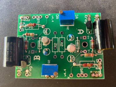
IA on the A side C4S board is reading 217,4 volts
IA on the B side C4S board is reading 265 Volts

Breg Regulator both sides is 217.4  and 217.6 respectively
-reg is 0
Kreg Regulator board is 9.7 Volts and 215 on the B side

Note, I was able to adjust the BIAS on one side just fine, the other side is not working.  No surprise there.  In addition, 2 out of the four leds on one board are not lit.  I am going to attempt to resolder that whoe board and hope to find my issues there.

I am most concerned about the resistance checks mentioned above and those tab are not connected to anything to start with. 
Any ideas where to start?
 
Regarding the 6.3V readings, remove the shielded twisted pair of wires that depart the 6.3V pads on the power supply PC board, then recheck those measurements.  If you don't see something around 50V and 56V, then you need to post some pictures of your power supply board.  If you do suddenly see 50V and 56V, then you have an issue with your heater wiring on one of the sockets, and one of the heater terminals is shorting to ground. 

IA on the A side C4S board and IA on the B side C4S board both connect to the positive output of the power supply board, so they cannot read different voltages like that.

Your Breg voltages are OK.

Having 215V at a Kreg terminal on the center PC board indicates a substantial miswire at the 6C45C socket that feeds or some kind of major wiring issue on the center board itself.

Please do not resolder that whole board, this is a miswire or two things touching that shouldn't be. 

It's completely possible that you have the connection for pin 7 on one 6C45 going to pin 6 instead.
 
I fixed the the 6.3 issue.  The + side is reading 57.03 volts and the - side is reading 51.6 volts.  was an old fashion cold solder.  They are both reading just fine now.    I will address the rest tommorrow or the next day,  I live on a lake and family is due in for the week end.  Will let you know.   
 
Ok, I got a little bit of time.  I have been able to get all resistance measurements within spec.

I also checked and rechecked the voltages after some careful reflowing of the solder

I now have the following measurements:

+275vDC on the Power Supply Board  271V
+6.3vDC on the Power Supply  57.6V
-6.3vDC on the Power Supply 51.5V
IA on the A Side C4S Board 269V
IA on the B Side C4S Board 266V
Breg Regulator (both sides)  217.4V and 217.6V
-reg Regulator (both sides)  0V
Kreg Regulator Board (both sides  9.8V and 3.2V

Obviously, there is still an issue on the (in this case) right side of the regulator board showing just 3.2V
In addition, the two leds are still not lit on the Right Cs4 board.  The power switch side.
 
I would imagine OB is also out of spec on one side...

The Kreg voltage being low is likely just because you still have a 6C45P that's not drawing any current, so the regulator is carrying it instead.
 
Understood.  As I stated in the beginning one set of leds were not lit and one pot had no affect. I did verify that the pot is working by ohming it out and turning the screw which caused resistance changes so I am pretty sure the pot itself is fine.  I  I think I should be getting close..    Now the question is where to look and verify the wiring and solder joints are correct.    My assumption is that the board that has 2 leds not turning on should be where I focus my attention.
 
No, I would focus on the center PC board where the little blue trim pots are, as well as the 6C45 socket under where the faulty voltage is.

If you believe the C4S board is at fault, you can try swapping them between sides to see if the problem follows one of the boards.  Generally the most common problem I see on those boards is insufficient heat on the center leg of the MJE5731A, and occasionally an error with jumper wires.
 
No, I would focus on the center PC board where the little blue trim pots are, as well as the 6C45 socket under where the faulty voltage is.

If you believe the C4S board is at fault, you can try swapping them between sides to see if the problem follows one of the boards. Generally the most common problem I see on those boards is insufficient heat on the center leg of the MJE5731A, and occasionally an error with jumper wires.
I swapped the C4S boards and the problem did not follow.. In addition, I checked the solder joint on the center pin of the MJE5731s and reheated it for good measure. The fact that the problem did not follow the boards confirms that they are ok. Looking at the regulator board closely does not present any issues with soldering or placement of jumpers or parts.. Both my wife and I have really looked for something out of place and cannot find anything. The initial problem persists and we still have low voltage on the Kreg on the B side of the regulator board of 3.2 volts as well as the two leds on the right c4s board above the C socket side that do not light up. Is it possible that one of the regulators has an issue? If so, it I were to flip the regulator board 180 degrees would that help to narrow it down?
 
Ok, I narrowed it down just a little bit more. I measured the resistance from one of the 470 ohm resistors to the center lug and jt measured 235 Ohms. I then did the second resistor and it measured exactly the same. Then when I measured from resistor across to the next is came up zero. I was a bit surprised there and thought the resistance would have doubled.. Then when I measured either side from the resistor to the attenuator it measured 235 again. This is consistent to both sides of the socket. I then did the exact same thing with the A socket and came up with exactly the same results. That tells me at least that part of the 6C45P socket is wired correctly. I will next remove the wires and caps from pins 4 and 5 and rebuild those to see what happens and let you know.
 
Nooooo, don't remove the wires and caps from pins 4 and 5. All you need to do to know whether those connections are good or not is to observe if the tube is glowing.
 
Not a problem. I didn't want to do that anyway, Yes the tube is glowing and the measurements are the same on both sides.... i.e. both the A and C sockets. In addition, I verified the wiring on the B socket. Nothing loose and all in correct positions.
 
Last edited:
You can rotate the center board 180 degrees and reinstall it. I'd imagine the issue will swap to the other side of the amp if you do that, which would confirm that there's either a bad solder joint or a wiring issue on the center board.
 
I did just that and the problem followed the board flip. Now, while I had the board off, I double checked all of the solder joints and reflowed a good number of them. The jumper wires are all correct. Potentially there could be a trim pot issue but as I stated earlier, it seemed to work with no power connected. In other words the resistance changed with I screwed one way of the other. on the pot. I think we are getting close.
 
Attached are photos of the front and back of the regulator board. Today after I removed the board from the base I did not clean the solder out of the attachment holes so don't worry about that. Note if you need higher quality, I can do that as well with my good camera instead of my phone. You should be able to zoom in either way. As stated earlier, we have narrowed the a problem down to this board. One side works and one side does not. There are only so many components on this board other than resistors. I checked each and every resistor and they are all fine That leaves one trim pot, transistor, and regulator per side. I can buy those pots either from Digikey or Mouser. In any event, I need to know the wattage for the part if you could provide me that. After the pots that I think are good a there is a transistor which I happen to have spares of from a previous project and I can order a regulator if needed. As far as the regulator in concerned I just need to know if it is .5% or 1% Thanks for all of your help and I will let you know the outcome.
 

Attachments

  • IMG_0647.jpg
    IMG_0647.jpg
    1.8 MB · Views: 5
  • IMG_0649.jpg
    IMG_0649.jpg
    1.6 MB · Views: 5
Last edited:
Back
Top