Replacement tube works, however, misaligned and smoky smell but ...[Solved]

TheCoolDoc

New member
Thanks for the replacement tube Bottlehead. Everything is working well now.
I just had a few questions:

1. Should I be worried that there is no smoke, however, a smoky smell? Maybe it's just the smell of hot electronics since I passed the resistance and voltage tests with flying colors.
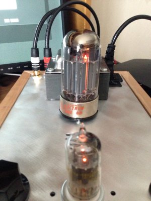
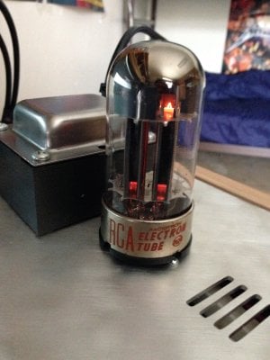
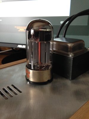
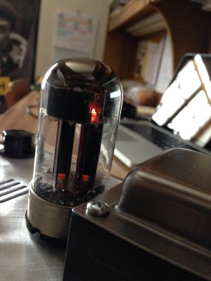
2. The replacement 6080 tube isn't "straight" what I mean is that the two towers inside are pointing to the left instead straight down towards the other tube (12AU7). I'll provide a pic, but everything is working and even music is playing. I made sure the pins were aligned correctly underneath the tube. It's just not symmetrical/

I'm about to install the speedball now and I have a feeling I'll face trouble in the process so I'll come back.


Attachments

  • IMG_0090.jpg
    IMG_0090.jpg
    2.1 MB · Views: 124
  • IMG_0089.jpg
    IMG_0089.jpg
    1.9 MB · Views: 131
  • IMG_0091.jpg
    IMG_0091.jpg
    703.7 KB · Views: 107
  • IMG_0092.jpg
    IMG_0092.jpg
    1.8 MB · Views: 93
I would suggest just enjoying the music for a while. I happen to love that "old electronics heating up" smell myself. Brings back a lot of fond memories of all the stuff I've played with over the years.
 
Doc B. said:
I would suggest just enjoying the music for a while. I happen to love that "old electronics heating up" smell myself. Brings back a lot of fond memories of all the stuff I've played with over the years.

I went ahead and bit the bullet Doc. Before I proceed with the voltage tests I just need someone's word.

The tubes are lighting up properly except 2 LEDs on the PCB are giving problems. One is very dim and another isn't lit at all.

Pics below because I can't name the LEDs properly. The first two pics depict the ones with the issues. The other two pics are completely fine, but there for reference.


Attachments

  • IMG_0095.jpg
    IMG_0095.jpg
    1.7 MB · Views: 129
  • IMG_0093.jpg
    IMG_0093.jpg
    1.7 MB · Views: 122
  • IMG_0094.jpg
    IMG_0094.jpg
    1.8 MB · Views: 106
  • IMG_0096.jpg
    IMG_0096.jpg
    1.6 MB · Views: 115
The LED on the large PCB board is definitely broken. It got separated from the wire itself and I can't fix that. The one on the "B" board, however, isn't working even after resoldering it.
 
OK firstly I get to plug a new spare LED pack we sell:

http://bottlehead.com/product/hlmp-6000-leds/

This should be helpful to those who have trouble sourcing the HLMP-6000s when they need a replacement.

Secondly, on the side that has the unlit, unbroken LED, check the solder joints on the MJE350 and 2N2907 transistors.
 
I had to remove the right LED on the large main board. I tried resoldering what you asked Doc, but still no light on the "B" board left LED.

Since I've removed the LED, it's brother is much brighter as should be expected.

Is there no way to check voltages or even hear music without an LED? I thought all LEDs did were help troubleshoot. Since the LED itself was destroyed, I assume most things should be connected properly?

Also, PB said to post voltages, which I still haven't tested, but should I?
 
TheCoolDoc said:
I thought all LEDs did were help troubleshoot.

No, they are an integral part of the constant current source.  If you left one out and applied power to the board, the board is not going to work.  It's hard to say with great certainty, but you may end up needing to replace that entire board at this point.
 
Caucasian Blackplate said:
No, they are an integral part of the constant current source.  If you left one out and applied power to the board, the board is not going to work.  It's hard to say with great certainty, but you may end up needing to replace that entire board at this point.

I only applied power for 2 seconds. I've placed an order for the LEDs. The LED was broken regardless if I removed it or not, so the connection was broken in the previous test attempts.

How can I test the boards themselves? At this point I'm considering returning to stock and calling it a day as the speedball is tedious.
 
Caucasian Blackplate said:
Replace the LED and run the board, that will be the most solid test.

-PB

I've replaced both LEDs, however, the one at the B board still doesn't light up. One is brighter than the rest on the main board. Pic below.
Should I run the voltage tests? I've turned the amp off. For clarification, all except left B are lit. Farthest left on big board is brighter than all.


Attachments

  • IMG_0107.jpg
    IMG_0107.jpg
    1.7 MB · Views: 97
Caucasian Blackplate said:
Yes, the voltage tests will now be valid with all the parts having been installed in the amplifier.

Alright thanks. Here goes. FYI, LED is still not on after resoldering some stuff.

I'll be back.
 
Caucasian Blackplate said:
Yes, the voltage tests will now be valid with all the parts having been installed in the amplifier.

Failure already. Got a huge spark at terminal 2. Terminal 1 gave me 125-130 V.

What to do? I've unplugged it.
 
Just noticed that the right LED on the left side of the main PCB takes a few seconds to light up and when this happens, its immediate left neighbor (which was immediately lit up) becomes brighter than the others. Takes maybe 5 seconds. All other ones turn on immediately.
 
You should proceed with the voltage checks.  If you are having trouble not shorting out neighboring terminals, wrap some tape around all but the tip of your red meter probe's metal end.

-PB
 
Caucasian Blackplate said:
You should proceed with the voltage checks.  If you are having trouble not shorting out neighboring terminals, wrap some tape around all but the tip of your red meter probe's metal end.

-PB

Terminal - Expected - Actual
1 - 75/90 - 0
2 - 170 - 126
3 - 0 - 0
4 - 170 - 130
5 - 75/90 - 0
6 - 0 - 0
7 - 100 - 45
8 - 0 - 0
9 - 100 - 25
10 - 0 - 0
11 - 0 - 0
12 - 0 - 0
13 - 170 - 125/130
14 - 0 - 0
15 - 185 - 165/170
20 - 0 - 0
21 - 206 - 203

Did the short circuit do something to terminals 1 and 5?
 
Caucasian Blackplate said:
Unplug the 6080, then try again.

-PB

Terminal - Expected - Actual
1 - 75/90 - 0
2 - 170 - 235/240
3 - 0 - 0
4 - 170 - 235/240
5 - 75/90 - 0
6 - 0 - 0
7 - 100 - 2/3
8 - 0 - 0
9 - 100 - 2/3
10 - 0 - 0
11 - 0 - 0
12 - 0 - 0
13 - 170 - 235/240
14 - 0 - 0
15 - 185 - 235/240
20 - 0 - 0
21 - 206 - 235/240
 
I would suspect that the center leg of each MJE-350 isn't adequately soldered.

It's tough to debug a situation like this, as you had your Crack operational for about a day before installing the Speedball, so there could be some underlying issue that has nothing to do with the Speedball itself. 

-PB
 
Back
Top