Quickie 1.1 (UPDATED - still no love but I was measuring wrong)
Dear Bottlehead Friends
A decade later, I finally built my Quickie 1.1 (gave my Quickie 1.0 to my kid for his dorm room so he can spin vinyl — knows how to get to his dad’s heart).
I spent way too many years trying to figure out how to do things like move the knobs off the top, the RCAs to the back, add a pair of inbound RCAs, use the Alps pot and fancy caps I got for it when I first bought the kit, and of course the most pressing question: what enclosure.
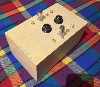
In the end I didn’t do any of that: I just built it into the box I’d been planning all along. The only difference is that I mounted directly to the top of the box instead of to the plastic chassis plate and put the batteries inside the box.
I’m attaching a picture of how pretty it turned out. But it’s also got something very wrong with it.
Some things first:
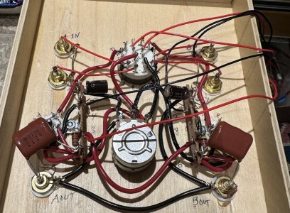
* I used those nifty screw-terminal power plugs to make it easy to separate the amp from the batteries. Later I will twist the power wires, but after it works. The correct voltages arrive at the terminals where the 3 power lines come in.
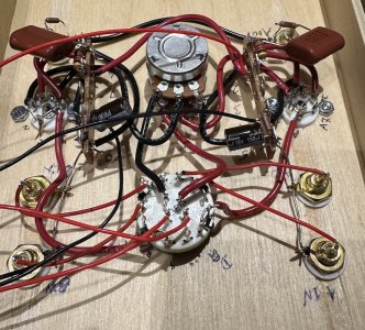
* I have gone over everything at least twice, walking through the instructions and checking the connections, re-soldering joins, looking closely at all the connections through a strong magnifying glass, comparing to the finished pic in the manual, and counting rotary switch numbers so often I can now count from 1 to 12 all on my own.
* I have two sets of tubes. Swapping doesn’t solve things.
* I have carefully ensured that the rotary switch is one click clockwise from leftmost when I test the voltages.
Clearly there’s something glaringly obvious that I’m simply not seeing.
So, here are the measurements.
Connection strip:
1: 0.L (same as leads in air)
6: 0.L
2: 0.L
7: 0.L
3: NC
8: NC
4: 1.07K ohms
9: 1.07K ohms
5: 0.1 ohms
10: 0 ohms
Rotary switch:
* 1: 0.L
* 2: 0.L
* 3: 91.3K ohms
* 4: 0.L
* 5: 0.L
* 6: 101.4K ohms
* 7: 0.L
* 8: 1.07K ohms
* 9: 1.07K ohms
* 10: 0.L
* 11: 1.07K ohms
* 12: 1.07K ohms
Pot:
* Closest to chassis B terminal 101.4K ohms (irrespective of knob position)
* Farthest from chassis B terminal 91.4K ohms (irrespective of knob position)
When I attach power, rotary switch to 1 click clockwise from full counterclockwise measurements:
* 1: 0 v
* 2: 0 v
* 3: 0 v
* 4: 0 v
* 5: 0 v
* 6: 0 v
* 7: 0 v
* 8: 3.945 v
* 9: 3.945 v
* 10: 0 v
* 11: 4.036 v
* 12: 4.036 v
* A: 0 v
* B: 0 v
* C: 3.942 v
* D: 3.942 v
I’ll note that switch terminals 1, 4, 7, 10 have no wires connected, but gosh I think this matches the manual.
I know it’s been a long time, but I’d be enormously grateful if someone could take a peek and seeing these values, instantly spot what I’ve overlooked.
Thank you,
__Roy
Dear Bottlehead Friends
A decade later, I finally built my Quickie 1.1 (gave my Quickie 1.0 to my kid for his dorm room so he can spin vinyl — knows how to get to his dad’s heart).
I spent way too many years trying to figure out how to do things like move the knobs off the top, the RCAs to the back, add a pair of inbound RCAs, use the Alps pot and fancy caps I got for it when I first bought the kit, and of course the most pressing question: what enclosure.
In the end I didn’t do any of that: I just built it into the box I’d been planning all along. The only difference is that I mounted directly to the top of the box instead of to the plastic chassis plate and put the batteries inside the box.
I’m attaching a picture of how pretty it turned out. But it’s also got something very wrong with it.
Some things first:
* I used those nifty screw-terminal power plugs to make it easy to separate the amp from the batteries. Later I will twist the power wires, but after it works. The correct voltages arrive at the terminals where the 3 power lines come in.
* I have gone over everything at least twice, walking through the instructions and checking the connections, re-soldering joins, looking closely at all the connections through a strong magnifying glass, comparing to the finished pic in the manual, and counting rotary switch numbers so often I can now count from 1 to 12 all on my own.
* I have two sets of tubes. Swapping doesn’t solve things.
* I have carefully ensured that the rotary switch is one click clockwise from leftmost when I test the voltages.
Clearly there’s something glaringly obvious that I’m simply not seeing.
So, here are the measurements.
Connection strip:
1: 0.L (same as leads in air)
6: 0.L
2: 0.L
7: 0.L
3: NC
8: NC
4: 1.07K ohms
9: 1.07K ohms
5: 0.1 ohms
10: 0 ohms
Rotary switch:
* 1: 0.L
* 2: 0.L
* 3: 91.3K ohms
* 4: 0.L
* 5: 0.L
* 6: 101.4K ohms
* 7: 0.L
* 8: 1.07K ohms
* 9: 1.07K ohms
* 10: 0.L
* 11: 1.07K ohms
* 12: 1.07K ohms
Pot:
* Closest to chassis B terminal 101.4K ohms (irrespective of knob position)
* Farthest from chassis B terminal 91.4K ohms (irrespective of knob position)
When I attach power, rotary switch to 1 click clockwise from full counterclockwise measurements:
* 1: 0 v
* 2: 0 v
* 3: 0 v
* 4: 0 v
* 5: 0 v
* 6: 0 v
* 7: 0 v
* 8: 3.945 v
* 9: 3.945 v
* 10: 0 v
* 11: 4.036 v
* 12: 4.036 v
* A: 0 v
* B: 0 v
* C: 3.942 v
* D: 3.942 v
I’ll note that switch terminals 1, 4, 7, 10 have no wires connected, but gosh I think this matches the manual.
I know it’s been a long time, but I’d be enormously grateful if someone could take a peek and seeing these values, instantly spot what I’ve overlooked.
Thank you,
__Roy