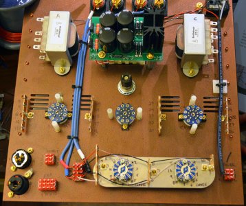
I'm pretty ashamed... I've had the Mainline and PreBee kits sitting on my "to-do" bench for far too long. I'm finally making some nice progress on the Mainline. There are some fun upgrades on the agenda... Jupiter capacitors, Cardas wiring, Teflon tube sockets, and a copper leafed wood base. Can't wait to hear Bottlehead's greatest new headphone amplifier.
You are using an out of date browser. It may not display this or other websites correctly.
You should upgrade or use an alternative browser.
You should upgrade or use an alternative browser.
Progress Report: Mainline coming along nicely!
- Thread starter HF9
- Start date
Strikkflypilot
New member
Fantastic clean look. Is the plate copper?
Hope You won't have the same issue that I had with teflons for the 9-pin sockets.
(The teflon gives a little when one tries to squeeze the small clamps together for better connection to tube pins, decided to go for ceramic with PCBs)
Hope You won't have the same issue that I had with teflons for the 9-pin sockets.
(The teflon gives a little when one tries to squeeze the small clamps together for better connection to tube pins, decided to go for ceramic with PCBs)
I didn't go with Copper for this particular build, just got an antique copper powdercoat. I did just get a copper plate for my upcoming Fix build though ")
It's amazing, there are so many different levels of quality of teflon sockets out there. I've ordered quite a few of them and have seen some great ones and some crappy ones. I always get them from the same company now. I think it was Valab. People like the CNC cut ceramic, and it's a great way to go. I like the Teflon as it offers a bit of natural damping. You can also get new Bakelite sockets if you want the vintage brownish color (there's probably no other reason for using Bakelite that I know of, the properties aren't as good on paper as Teflon or ceramic).
It's amazing, there are so many different levels of quality of teflon sockets out there. I've ordered quite a few of them and have seen some great ones and some crappy ones. I always get them from the same company now. I think it was Valab. People like the CNC cut ceramic, and it's a great way to go. I like the Teflon as it offers a bit of natural damping. You can also get new Bakelite sockets if you want the vintage brownish color (there's probably no other reason for using Bakelite that I know of, the properties aren't as good on paper as Teflon or ceramic).
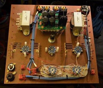
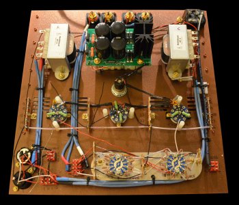
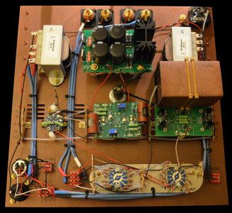
More pics as promised. Finished up the attenuator wiring and a few other things. That Cardas wire requires a bit of patience. On each side you strip off the jacket, strip off a layer of teflon, wind up the shield, remove another layer of dielectric, then another layer of teflon, then you burn the enamel off the wiring before installing. It's definitely a labor of love ") It does sound great though, love that nice warm sound.
It does sound great though, love that nice warm sound.
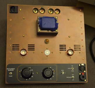
On the top you'll see the rivets are just for looks. The volume knobs are temporary, I still need to order the Kilo black aluminum ones I like.
It does sound great though, love that nice warm sound. On the top you'll see the rivets are just for looks. The volume knobs are temporary, I still need to order the Kilo black aluminum ones I like.
Attachments
Grainger49
New member
Extremely nice work. I like the shrink tubing on the cables.
PassionForSound
New member
Wow! I don't get over to this forum much anymore (most of my time is on Head-Fi), but your Mainline build is simply stunning, HF9!! Very steampunk!
 I can use my matching steampunk Grado's with it when it's done
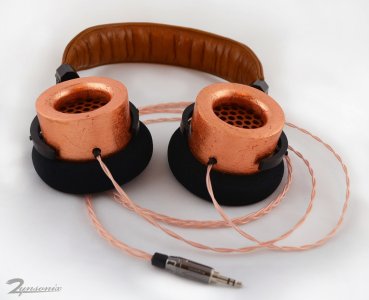
Strikkflypilot
New member
Fantastic work. Really something to aspire to. And the PCB soldering looks superior to the manual build.
Thanks ;D Purists will say that you're potentially degrading things by forcing the connections through a PCB rather than soldering directly to the pins, but I've found the extra room for soldering makes things a bit easier and cleaner looking.Strikkflypilot said:Fantastic work. Really something to aspire to. And the PCB soldering looks superior to the manual build.
Grainger49
New member
That is stunning work.
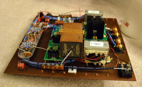
Just about done, just need a Kilo knob and one of the Z5U caps I'm waiting for in the mail, then I can start testing. The Jupiter capacitor mounting required some thought. I initially was going to mount a piece of FRP material then mount the caps to that, however I ended up with a standoff and a capacitor mount instead, it offered a slightly cleaner look. The cap narrowly avoids touching the transformer and the clip on heatsinks.
Attachments
Strikkflypilot
New member
Thank You for these pics!
Such an impressive build. You even managed to fit those Jupiters...
Such an impressive build. You even managed to fit those Jupiters...