Problem Seduction pre-amp_radio station in background

choff

New member
Hello,

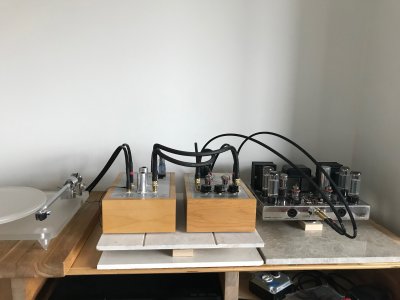
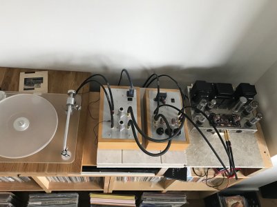
I recently moved my listening room to another location in my house.  Unfortunately, I now have a local radio station playing (fairly loudly) in the background during playback of records with my Seduction amp run thru a Foreplay to a Dynaco 70.  I have no idea what to do to correct this issue?  Tried searching forum but couldn't find any relevant topics. Would really appreciate any feedback or suggestions. Thank you.

Carl
 
No, the radio station noise remains.  It only goes away when I remove the output cables going to the Foreplay.
 
Can you try temporarily connecting the chassis plates of the Seduction and Foreplay together with a piece of wire. 

It might also help to see the build underneath the Seduction, but if you're getting the radio station in both channels, it's doubtful that there's something unusual in the build. 

What may end up being helpful is adding 100-330pF of capacitance across each 47K resistor across the input jacks, or pursue additional shielding of the base (you are using the tube shields I presume).
 
I am indeed getting the radio signal in both channels.  I am using the tube shields. This Seduction amp has worked flawlessly for me since I built it about 8 years ago.  How would I connect the chassis with a wire?  How would I shield the base?  Can you explain a little further how I would perform this task.....100-330pF of capacitance across each 47K resistor across the input jacks.  I am pretty good at following instructions but don't know or understand all the inner workings of these amps.  Thanks for your feedback and assistance!!
 
To do the wire experiment, use a piece of wire and touch it on the ground post of the Seduction and the chassis of the Foreplay.

The Seduction was originally designed so that a Hammond metal box could be mounted over the circuit (you have to file out parts of the box where the wires come and go).  So few folks needed this that it barely came up, but it's an option.

On each input RCA jack, there's a 47K resistor from the center post to the ground buss.  To add the capacitors, solder one end of each cap to the end of the 47K resistor going into the center post of each input RCA jack, then solder the other end to the ground plane (or the other end of each 47K resistor that connects to the ground plane).
 
Thanks for the reply.  I tried the wire and it reduced the amount of the sound, but did not eliminate it.  Probably cut it in half to 3/4.  It seemed to work best if i layed the bare wire across the face of the chassis rather than just touching at a point.

Any further thoughts on how to proceed?  Is there anything that might be causing this as far as the house wiring, or is that not associated with this type of problem.  Thanks again....much appreciated.
 
A box covering the underchassis circuitry is the solution we proposed for this problem originally (17 years ago), so it probably makes sense to try that next. IIRC a Hammond 1590J was what we suggested, but I don't recall if that accommodates the C4S board or just fits the basic circuit.
 
Also at some point the screw holes for the Hammond box were removed from the chassis since no one ever seemed to actually need them. A picture would help here.

Is there any space in the setup to try different positioning/orientations...?
 
It looks like you have the holes for the Hammond box (though perhaps with some added screws?).

The ground connection that you added should have been in the preamp, but IIRC the original Foreplay preamps didn't have signal ground tied to chassis.  I believe the recommendation was to jumper terminal 13 to terminal 14 to make this connection (which is now standard on all of our preamps).

 
Hope these pics help clarify things.  Unfortunately, I am pretty locked into the layout of the system without much flexabilty to make changes, unless you see something I can easily tweak to improve the situation.  I do have CS4 in the Seduction. 

I will also note that the new location is a room in an addition on top of my house.  It is lightweight framing with alluminum cladding on the exterior, whereas the original room was lower and masonry exterior wall construction.  I imagine this higher more transparent location is allowing the radio signal to get to the amp more easily?
 

Attachments

  • IMG-3060.JPG
    IMG-3060.JPG
    1.6 MB · Views: 20
For some reason it won't let me upload the image? I'll keep trying, but it looks like I already have the Hammond. 
 
The plot thickens, as you already have the shield box on there. Tighten up the chassis safety ground screw next to the IEC input to be sure that's not creating any extra resistance. Is the Seduction plugged right into the wall socket, or is it plugged into some form of power strip or conditioner? Also, has your Stereo 70 been converted to a three wire (safety grounded) power cord?
 
I see tons of places you could put it: 
Rotate it 90° and put it behind the table.
Rotate to whatever angle works in its current position.
Add a wall shelf above.
Move the CD player up, put the Seduction in the cubby that holds the CD player now.
Swap locations b/t the tt and power amp so your system goes right-to-left instead of left-to-right.

Those are the obvious ones from the pictures shown.

What you want to do is plug in just the Seduction and move it around and see if you can minimize the pickup, then rearrange the system to suit the placement.

Also worth noting that I was picking up radio for a while in my system. When I isolated it, it turned out that I had a bad solder joint on the ground of my stepup transformer. It's possible that the problem is revealing itself now not because the system has been moved, but because in moving it, you jostled a dodgy solder connection.
 
Doc B. said:
The plot thickens, as you already have the shield box on there. Tighten up the chassis safety ground screw next to the IEC input to be sure that's not creating any extra resistance. Is the Seduction plugged right into the wall socket, or is it plugged into some form of power strip or conditioner? Also, has your Stereo 70 been converted to a three wire (safety grounded) power cord?

It's plugged directly into a dedicated line wall outlet.  Dynaco has been converted.  All components have their own dedicated wall outlet line run back to the electric panel. 
 
There may be certain 6922 tubes that are less prone to RFI pickup than others. Unfortunately I don't have any experience to share about that. Something I would probably try if it were my system is wrapping the tubes around the cylindrical part (not over the top) with adhesive backed copper tape, then soldering a drain wire to the tape that attached to one of the tube socket screws. Aluminum tape like you can get in the HVAC section of Home Depot might work too, but of course you wouldn't be able to solder the wire to the alu. Just tape the drain wire to the foil with another piece of the aluminum tape. Try to keep it neat so you can still fit the shield can on. Removing the spring from the shield might help gain some clearance. The spring is not absolutely necessary.

 
I tried tightening the screw but nothing changed.  It was already pretty tight.  One odd thing I noticed while doing this is that if I put my hand held in a vertical position between the Dynaco and the Foreplay the sound from the radio was significantly diminished.  Could that be a clue to anything? 
 
Back
Top