You are using an out of date browser. It may not display this or other websites correctly.
You should upgrade or use an alternative browser.
You should upgrade or use an alternative browser.
Pre-made power supply for Quickie
- Thread starter boulos
- Start date
I've spent some time tracing the circuit and voltages. I can trace a direct path (of decreasing potential while the Quickie is off) from IB to ground. Specifically:
IB -> D1 -> R @D2 -> R2 -> R3 -> R between T9 and Ground
The voltages along this path are:
35.14 -> 34.71 -> 34.45 -> 5.54 -> 0.26 -> 0
This means that current is flowing along this path and the batteries drain slowly over time.
I carefully checked all the solder joints and they looked OK. However, I can also trace this same path in the manual's pictures (page 22 makes that possible).
As far as I can tell from the PJCCS manual, this problem doesn't exist in the Original Quickie because IB input voltage is governed by the on/off switch, whereas in Quickie 1.1 IB is always connected.
Grainger49
New member
A little background information:
The design would have it where the voltage for the heaters turns on (causes flow through) the tube. The "high voltage" will not pass unless the heater is hot.
So, without terminal or tube pin numbers that means that the positive supply will stack up on the plate of each tube. It goes nowhere and there is no drain on the batteries. It is like "seeing" an open switch. The heaters are on the switch; in the off position they do see an open switch.
I would be pulling out the manual but my mind is too fuzzy this morning.
Hi Grainger,
The positive supply is behaving as intended (and as you describe). However, it appears to be "leaking" via -reg to ground through the path I described in my earlier post (when the Quickie is off with and without tubes attached). I double and triple checked my work, and as far as I can tell, the same path exists in the manual. I am stumped at this point.
The positive supply is behaving as intended (and as you describe). However, it appears to be "leaking" via -reg to ground through the path I described in my earlier post (when the Quickie is off with and without tubes attached). I double and triple checked my work, and as far as I can tell, the same path exists in the manual. I am stumped at this point.
Grainger49
New member
I'll need to get out a PJCCS manual and look at it.
And there it is, on page 17 and 18 of the manual I have the high voltage (36V) is switched through the center contacts of the three pole double throw power toggle switch. There should be no leakage through the boards when the switch is off.
You can test this by measuring the center two lugs that are used of the power switch. Test for voltage when it is closed, should be zero V. Then test for voltage when open, should be the full voltage of your 9V battery string.
If it is not zero volts when off there is the leakage.
Gerry E.
Member
Hi:
I have a vested interest in knowing what happened. Boulos had lent me his Quickie. I used it for a couple of days (side note - it sounded amazing, especially for the cost!) but then went back to my BeePre. It sat on my shelf for a couple of weeks before I returned it to Boulos.
Recently I found out that when I returned it to Boulos, the batteries were dead. My first thought was that I must have screwed up and left it on, though I'm usually pretty careful when it comes to things like that. Especially when it's not mine!
Boulos said no, that it was switched off when I returned it. That makes more sense and I felt better knowing that.
Gerry
4
4krow
Guest
I would like to add that on one of my Quickie projects, I used double knife (think old fashioned double pole) switches. At the time, I didn't even think about it when I hooked up both sides of the 9 volt battery supply to these switches. To be clear, I had two double pole switches, so the 9 volt AND the D cells were controlled by them. Both sides of the 9 volt batteries (positive and negative), and maybe only one side of the D cells IIRC. I guess what I am driving at is I never had an issue that was battery related. On the other hand, this idea only masks any possible symptoms rather than solve them.
Hi Greg, The switch indeed masks any issues, but effectively solves the problem. I would rather not add another switch though.
One way to verify I'm not crazy is: if someone has an unmodified Quickie 1.1 with PJCCS, and a precise voltmeter (I am using a BK Precision 2709B), then please measure -reg on the PJCCS when the Quickie is off and the batteries are installed (the newer the better to get a higher measurement). The measurement will be about 0.25V.
One way to verify I'm not crazy is: if someone has an unmodified Quickie 1.1 with PJCCS, and a precise voltmeter (I am using a BK Precision 2709B), then please measure -reg on the PJCCS when the Quickie is off and the batteries are installed (the newer the better to get a higher measurement). The measurement will be about 0.25V.
Bumping this thread up. Since I use the Quickie occasionally, solving this issue is important for me and preferable over taking out a 9V battery every time I'm done listening. Can anyone else with a stock Quickie 1.1 + PJCCS measure -reg when the Quickie is off. I'm getting ~0.25V which means the batteries are constantly draining?
Thanks
Boulos
Thanks
Boulos
Hi,
If you use it daily, then the leakage when it's off will be irrelevant for you. It becomes relevant when you keep it off for a while (weeks at a time), then turn it on and find that the batteries have been drained enough that they're no longer usable.
Measure -reg (on the PJCCS board) to ground (with an instrument that can measure small voltages). I get 0.25V. From earlier in the thread, here's the path and list of measurements I took (all to ground):
IB -> D1 -> R @D2 -> R2 -> R3 -> R between T9 and Ground
The voltages along this path are:
35.14 -> 34.71 -> 34.45 -> 5.54 -> 0.26 -> 0
This means that current is flowing along this path and the batteries drain slowly over time.
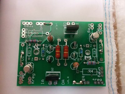
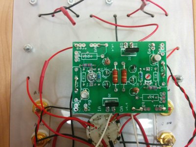
This is resolved now. It turns out there was an error in the PJCCS manual for the Quickie 1.1. Thanks to PB for the excellent support, for identifying the issue and sending me the fix. After updating the board based on the new instructions, there is no more parasitic current leak. As a test, I left the batteries in the Quickie for almost two months while it's off, and they measured the same as when I put them in. Attached are pics of the updated PJCCS board.
Attachments
Similar threads
- Replies
- 3
- Views
- 5K